
Method and system for predictive maintenance of integrated circuits

An integrated circuit, predictive technology, applied in the direction of digital circuit testing, electronic circuit testing, using electrical devices, etc., can solve problems such as time-consuming and cost-effective, and achieve the effect of avoiding downtime, saving costs, and reducing costs

Active Publication Date: 2020-03-17
SIEMENS AG
View PDF8 Cites 0 Cited by
  • Summary
  • Abstract
  • Description
  • Claims
  • Application Information

AI Technical Summary

Problems solved by technology

[0009] However, this approach has the disadvantage that manufacturer data for integrated circuits, such as maximum failure rates, etc. are usually based on average or median values ​​of, for example, reliability tests and / or stress tests at elevated temperatures and / or voltages, etc.
However, in the case of this method, a relatively and possibly time-consuming and cost-intensive analysis is required due to the large amount of information

Method used


Image

  • Method and system for predictive maintenance of integrated circuits
  • Method and system for predictive maintenance of integrated circuits

Examples


Embodiment Construction

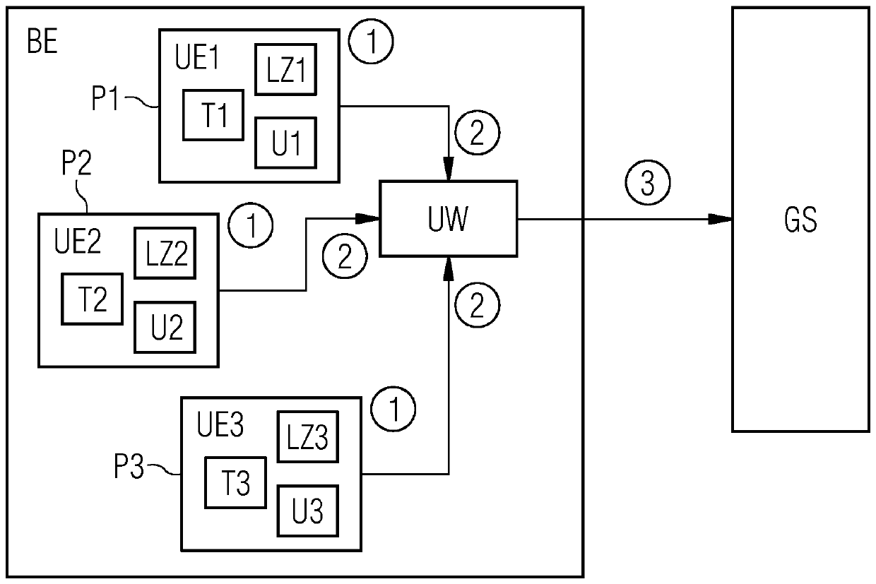
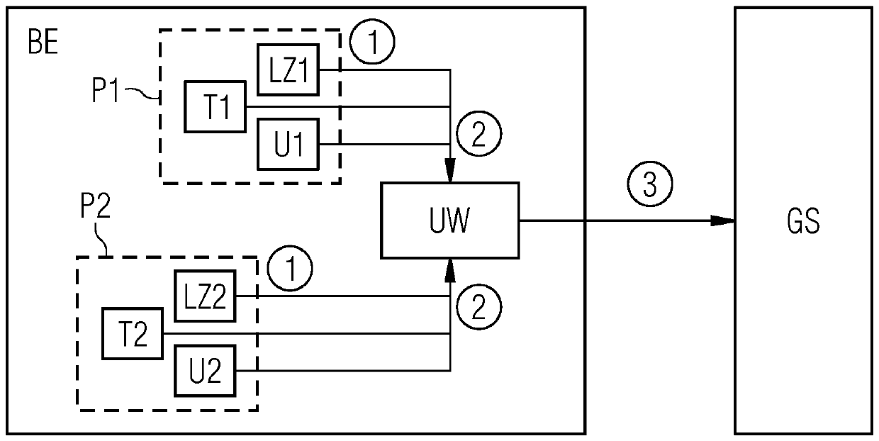
[0033] figure 1 An exemplary electronic device BE is shown schematically. The device BE is implemented as an integrated circuit, for example as an application specific integrated circuit or ASIC. Alternatively, however, the electronics BE can also be embodied as a so-called Field Programmable Gate Array (Field Programmable Gate Array) or FPGA. The electronics BE can be, for example, a system component or a part of a system component in the overall system GS, which serves as a superordinate layer and is designed, for example, as an embedded system GS.

[0034] Among other things for simplicity in figure 1 Outside of units not shown, the figure 1 The electronic device BE shown in exemplarily has a plurality of sensors T1, U1, LZ1, T2, U2, LZ2 at two exemplary positions P1, P2, these sensors are mounted for example on the semiconductor material of the electronic device BE or integrated circuit middle. Current values ​​of system parameters, such as temperature and voltage as ...


PUM


Abstract

The invention relates to a method for the predictive maintenance of electronic components (BE) and to an associated system. The electronic components (BE) to be maintained are in the form of integrated circuits, in particular application-specific integrated circuits (ASICs) or what are known as field-programmable gate arrays (FPGAs). For this purpose, an electronic component (BE) to be maintainedhas sensors (T1, U1, LZ1, T2, U2, LZ2) at at least one position (P1, P2), by means of which sensors present values of system parameters, such as temperature and voltage, and of a signal propagation time at the at least one position (P1, P2) are determined during operation. The values of the system parameters and of the signal propagation time presently determined by the sensors (T1, U1, LZ1, T2, U2, LZ2) at the at least one position (P1, P2) are retrieved (1) by a central monitoring unit (UW) installed in the electronic component (BE). By means of the central monitoring unit (UW), an individual valid limit value is then determined for the signal propagation time at each of the at least one position (P1, P2) on the basis of the presently determined values of the system parameters and the presently determined signal propagation time at each of the at least one position (P1, P2) is compared (2) with the associated valid limit value. If the present signal propagation time exceeds the limitvalue, a notification is sent (3) to a superordinate level (GS), such as the overall system, in order, for example, to trigger an early replacement of the electronic component (BE) and thus to prevent error states and failures.

Description

technical field [0001] The present invention relates generally to the field of electronic systems and circuits, and more particularly to the field of integrated circuits, such as application-specific integrated circuits (ASICs) and field-programmable gate arrays (FPGAs). In particular, the invention relates to a method for predictive maintenance of electronic devices implemented as integrated circuits, in particular ASICs or FPGAs. The electronic component has sensors at at least one location, from which system parameters and signal transit times are determined at the at least one location during operation of the electronic component. Furthermore, the invention also relates to an associated system for predictive maintenance of electronic components. Background technique [0002] In many complex systems, such as control and regulation systems for machines and installations, computer systems, production facilities, vehicles and aircraft, propulsion plants, etc., especially in...

Claims


Application Information

Patent Timeline
Patent Type & Authority Applications(China)
IPC IPC(8): G01R31/28G01R31/317G06F11/00
CPCG01R31/2856G01R31/2882G01R31/31725G06F11/00G06F2119/04G01K13/00G01K2217/00
Inventor M.马特施尼格F.艾彭斯泰纳B.菲舍尔M.嘉米施路T.欣特斯托赛尔H.陶赫尔
Owner SIEMENS AG
Learn More