Chassis digital speed changing device of cloth rolling machine

A technology of speed change device and cloth winding machine, which is applied in the direction of winding strips, transportation and packaging, thin material processing, etc., and can solve the problems of affecting the work of the encoder, affecting the rotation of the rotating end, and easy entry of impurity fibers, etc.

Inactive Publication Date: 2020-03-20
钱俊峰
View PDF0 Cites 0 Cited by
  • Summary
  • Abstract
  • Description
  • Claims
  • Application Information

AI Technical Summary

Problems solved by technology

[0003] The disadvantage of the digital speed change device of the general cloth winding machine is that it is normal to have fine impurity fibers in the fabric environment, and the encoder used in the digital speed change device generally generates a signal through the rotation of the rotating end to generate angular displacement. To change the speed, but generally there is a gap at the position where the rotating end of the encoder passes through the housing, and this gap is generally exposed to the outside, and it is easy to enter impurity fibers, which will affect the rotation of the rotating end after a long time, thus affect the work of the encoder

Method used


Image

  • Chassis digital speed changing device of cloth rolling machine
  • Chassis digital speed changing device of cloth rolling machine
  • Chassis digital speed changing device of cloth rolling machine

Examples


Embodiment Construction

[0019] The following will clearly and completely describe the technical solutions in the embodiments of the present invention with reference to the accompanying drawings in the embodiments of the present invention. Obviously, the described embodiments are only some, not all, embodiments of the present invention. Based on the embodiments of the present invention, all other embodiments obtained by persons of ordinary skill in the art without making creative efforts belong to the protection scope of the present invention.

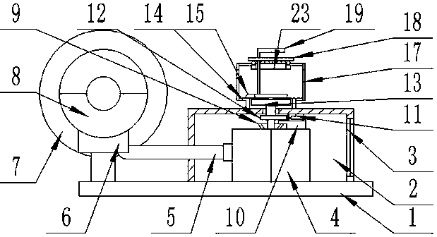
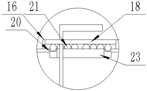
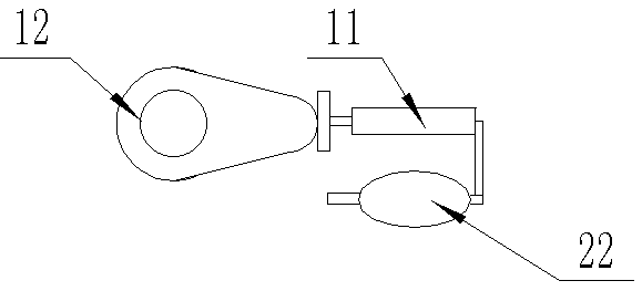
[0020] see Figure 1-4 , the present invention provides a technical solution: a chassis digital transmission device of a cloth winding machine, including a chassis 1, a reel 7 is provided on the left side of the upper end surface of the chassis 1, a motor 8 is provided at the front end of the reel 7 and the motor 8 is fixedly connected to the chassis 1, and the main shaft of the motor 8 is connected to the reel 7 at the same time. It is a code disc type, and ...


PUM


Abstract

The invention discloses a chassis digital speed changing device of a cloth rolling machine. The chassis digital speed changing device comprises a chassis, wherein a winding drum is arranged on the left side of the upper end surface of the chassis. A motor is arranged at the front end of the winding drum and is fixedly connected to the chassis. A spindle of the motor is connected with the winding drum. A protective box is fixedly connected to the right side of the upper end surface of the chassis. An encoder is fixedly connected in the protective box and is an encoding disc. Meanwhile, the rotating end of the encoder is vertically upward. A driving disc rotates outside a protective cylinder. Therefore, an inner rotating disc is driven to rotate. Corresponding-degree rotating is carried outaccording to a number indicated by a pointer, the rotating disc drives the rotating end of the encoder to be subjected to angular displacement, the encoder converts the displacement into an electric signal, and then the electric signal is converted into a counting pulse to act a rotating speed controller of the motor. The rotating process of the rotating end of the encoder is carried out under theprotective environment with the protective box and the protective cylinder, so that fine impurity fibers are prevented from entering the rotating end and penetrating out of a gap in an encoder shellin the cloth rolling process.

Description

technical field [0001] The invention relates to the technical field of speed change of a cloth winding machine, in particular to a digital speed change device for a chassis of a cloth winding machine. Background technique [0002] Generally, after the cloth is manufactured, it needs to be wound on the roller shaft by the cloth winder and stored, and the roller shaft for winding the cloth will adjust the winding speed according to the workload and other conditions, and the change of the speed is mainly through The transmission, in order to avoid the complexity of the mechanical gear transmission, adopts the digital transmission device with the function of the encoder; [0003] The disadvantage of the digital speed change device of the general cloth winding machine is that it is normal to have fine impurity fibers in the fabric environment, and the encoder used in the digital speed change device generally generates a signal through the rotation of the rotating end to generate ...

Claims


Application Information

Patent Timeline
Patent Type & Authority Applications(China)
IPC IPC(8): B65H18/00B65H75/30
CPCB65H18/00B65H75/30
Inventor 钱俊峰
Owner 钱俊峰
Why Eureka
Try Eureka