Screw rod of plastic extruding machine

An extruder and screw technology, applied in the field of extruders, can solve the problems of affecting the effect of melting, reducing the quality of recycled plastics, and poor applicability, so as to achieve good melting effect, improve quality, and increase quality.

Active Publication Date: 2020-03-24
江苏大维塑料技术(集团)有限公司
View PDF21 Cites 0 Cited by
  • Summary
  • Abstract
  • Description
  • Claims
  • Application Information

AI Technical Summary

Problems solved by technology

[0003] 1. Existing extruders can be roughly divided into three areas in the axial direction according to different physical functions: solid conveying area, melting area and melt conveying area, but as the plastic waste is transferred from the solid conveying area to the melt conveying area During the moving process, due to the continuous heating and melting of plastic waste, the space occupied by it gradually becomes smaller. In order to make the melted plastic liquid more compact and compact, the most traditional extruder screw is to use the melting zone of the screw. The depth of the thread groove between the melt delivery area and the melt delivery area is reduced, and the root diameter of the screw is increased, thereby reducing the volume of the thread groove. However, the depth of the thread groove of such a screw is processed and is a fixed value, which can only be used for Some suitable plastics will work better, but different plastics have different requirements for the depth of the thread groove after melting, so the traditional screw is difficult to adapt to different types of plastics, and different types of plastics need to be replaced for different types of plastics. screw, poor applicability
[0004] 2. The extruder heats the plastic in the cylinder body through electromagnetic induction through the electromagnetic coil connected to the outside of the cylinder body, so the stirring effect inside the cylinder body will directly affect the uniformity of heating. Thereby affecting the degree of melting of the plastic, but because the screws of the existing extruders are smooth, whether it is for the unmelted plastic waste that has just entered the barrel or the liquid that is melted in the later stage, the smooth inner wall will affect its The effect of stirring is not good, and the effect of stirring in the solid conveying area is not good, which will affect the uniformity of its heating, thereby affecting the effect of its melting, so that the incompletely melted raw plastic waste cannot contact the cylinder faster to be heated and completely melted , and for the completely melted plastic liquid, it is necessary to reduce the space of the thread groove to ensure that the plastic liquid in the thread groove can be compacted more tightly, but due to the existence of pressure, it will inevitably make it difficult for some molten plastic liquid to Moving, coupled with the smooth screw, the stirring effect is not good. After a long time, it will directly cause the plastic liquid to stay in it for too long, and the plastic liquid will decompose or even burn in it, and adhere to the inner wall of the cylinder, which will greatly affect the Improve the heat transfer performance of the cylinder, and also reduce the quality of subsequent recycled plastics

Method used


Image

  • Screw rod of plastic extruding machine
  • Screw rod of plastic extruding machine
  • Screw rod of plastic extruding machine

Examples


Embodiment Construction

[0020] The following will clearly and completely describe the technical solutions in the embodiments of the present invention with reference to the accompanying drawings in the embodiments of the present invention. Obviously, the described embodiments are only some, not all, embodiments of the present invention. Based on the embodiments of the present invention, all other embodiments obtained by persons of ordinary skill in the art without making creative efforts belong to the protection scope of the present invention.

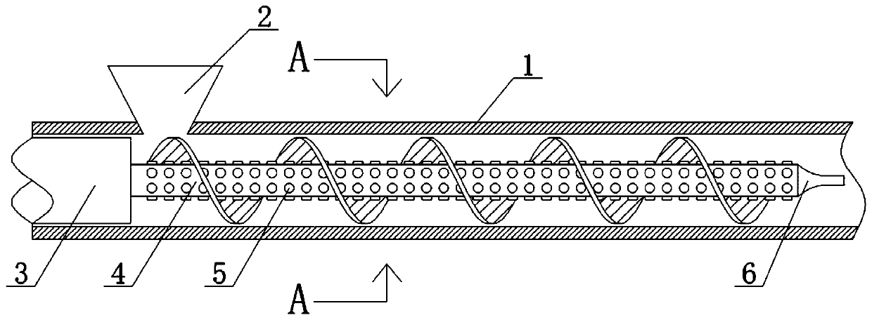
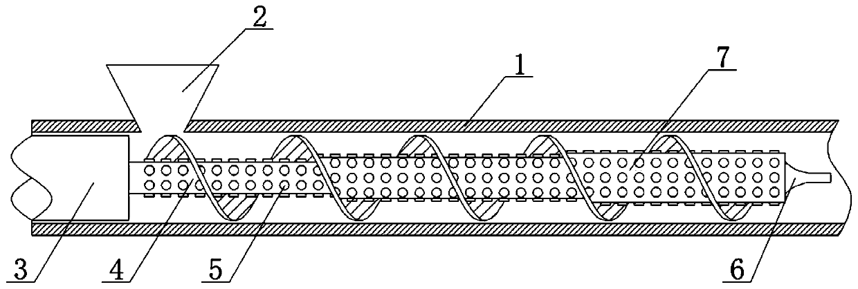
[0021] see Figure 1-5 , a screw rod of an extruder, comprising a cylinder body 1, a feed hopper 2 is fixedly installed on the top of the cylinder body 1, a connecting shaft 3 is fixedly installed on one side inside the cylinder body 1, and a rotating shaft is fixedly installed on one end of the connecting shaft 3 4. The rotating shaft 4 is fixedly provided with a first round protrusion 5 , one end of the rotating shaft 4 is fixedly mounted with a screw head 6...


PUM


Abstract

The invention relates to the technical field of plastic extruding machines, and discloses a screw rod of a plastic extruding machine. The screw rod comprises a cylinder body. A feeding hopper is fixedly mounted at the upper part of the cylinder body; a connecting shaft is fixedly mounted at one side in the cylinder body; and a rotating shaft is fixedly mounted at one end of the connecting shaft. According to the screw rod of the plastic extruding machine, a traditional threaded rod with a changed root diameter is changed into a threaded rod with a consistent root diameter, thickening plates are additionally arranged in a threaded groove of the threaded rod, and the depth of the threaded groove is changed by increasing the number of the overlaid thickening plates, and volume size is changed, so that the depth of each threaded groove on the rotating shaft can be freely controlled; no thickening plate is additionally arranged or a small number of thickening plates are additionally arranged in a solid conveying area, and the number of the thickening plates additionally arranged in the direction of the axial direction towards a melt transport zone can be gradually increased, so that thecompaction effect can be achieved, and the subsequent discharging quality can be improved; and the number of the thickening plates can be freely increased or decreased according to different kinds ofplastic so that the best production requirement can be met, and the product quality can be improved to the maximum degree.

Description

technical field [0001] The invention relates to the technical field of extruders, in particular to a screw of an extruder. Background technique [0002] In the plastic machinery, the extruder occupies a very important position. Most of the plastic products can be realized by extruding the extruder, and the core part of the extruder is the screw. Entering the extruder, the motor drives the screw to rotate, so that the screw drives the plastic waste to move in it, and the external electromagnetic heating coil heats and melts the plastic, making it a fluid plastic liquid that is extruded from the outlet of the extruder. But there are always some problems with existing extruders: [0003] 1. Existing extruders can be roughly divided into three areas in the axial direction according to different physical functions: solid conveying area, melting area and melt conveying area, but as the plastic waste is transferred from the solid conveying area to the melt conveying area During t...

Claims


Application Information

Patent Timeline
IPC IPC(8): B29C48/505B29C48/59
CPCB29C48/505B29C48/59
Inventor 魏砚广
Owner 江苏大维塑料技术(集团)有限公司
Why Eureka
Try Eureka