Elastic Clay Buffer for Metro Vehicles
What is Al technical title?
Al technical title is built by PatSnap Al team. It summarizes the technical point description of the patent document.
A technology of elastic clay and buffer, which is applied in the direction of buffer, railway car body parts, solid shock absorber, etc., can solve the problems of steep characteristic curve, high static impedance, high initial resistance, etc., to meet performance requirements, The effect of high sealing reliability and low initial resistance
Active Publication Date: 2021-01-05
BEIJING INST OF STRUCTURE & ENVIRONMENT ENG +1
View PDF5 Cites 0 Cited by
Summary
Abstract
Description
Claims
Application Information
AI Technical Summary
This helps you quickly interpret patents by identifying the three key elements:
Problems solved by technology
Method used
Benefits of technology
Problems solved by technology
[0004] At present, subway buffers are mainly equipped with elastic cement buffers and elastomer buffers. In order to maintain good low-temperature resilience, the existing elastic cement buffers require a high initial filling pressure, which will lead to High initial resistance, in order to reduce the initial resistance, the existing elastic cement buffer has multiple sets of disc springs connected in series, and after the disc springs are connected in series, the characteristic curve rises sharply at the critical point of displacement
The existing elastomer buffer has the advantages of free maintenance, light weight, and relatively high reliability, but it also has disadvantages such as aging creep, relatively low absorption rate, high static impedance, and short life.
Method used
Image
Click on the blue label to locate the original text in one second.
Reading with bidirectional positioning of images and text.
Examples
Embodiment Construction
[0031] The structure of the present invention will be further described below in conjunction with the accompanying drawings.
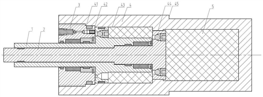
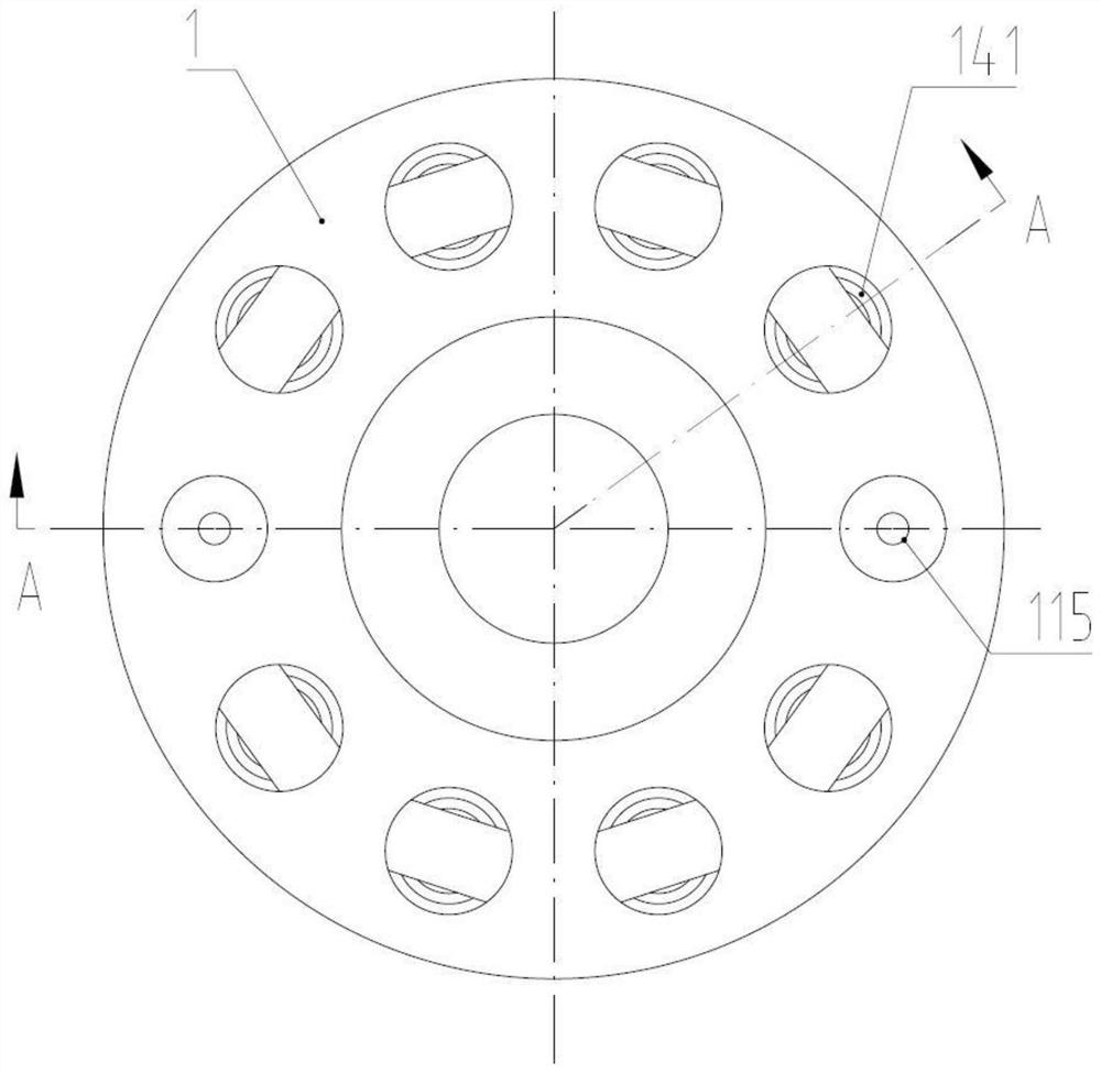
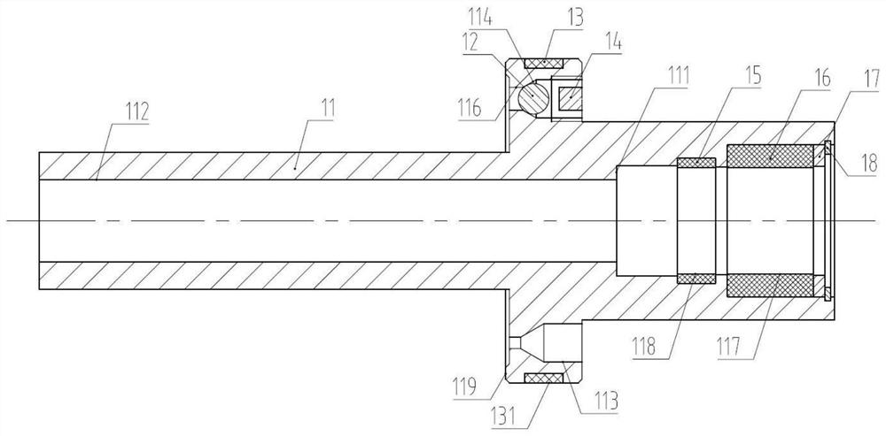
[0032] refer to figure 1 As shown, the patented product of the present invention includes an outer piston rod component 1 coaxially installed together, an inner piston rod component 2, a cylinder head component 3, a cylinder body 4 and an elastic cement material 5 that is pressure-packed inside the cylinder body 4 . A damping slit flow 44 is set between the inner piston rod component 2 and the cylinder body 4, the fourth guide belt 13 installed on the outer piston rod component 1 slides and fits with the inner wall 43 of the cylinder body 4, and the cylinder head component 3 Axial positioning is realized with the cylinder body 4 through the positioning surface 42. The radial positioning of the cylinder head component 3 and the cylinder body 4 is realized through the positioning surface 41. The outer diameter of the cylinder body 4 is provided with a st...
PUM
Abstract
The invention discloses an elastic daub buffer of a subway vehicle. The damper comprises an outer piston rod assembly, an inner piston rod assembly, a cylinder cover assembly, a cylinder body and elastic cement gum, the outer piston rod assembly comprises an outer piston rod, an outer guide belt, a one-way valve steel ball, a positioning flat plug in threaded connection, an inner guide belt, a sealing piece, a positioning ring and an elastic check ring, the inner piston rod assembly comprises an inner piston rod, a guide belt, a one-way valve steel ball and a positioning flat plug in threadedconnection. The cylinder cover assembly comprises a cylinder cover, a static sealing piece, a dustproof ring, a sealing piece, a guide belt, a guide ring, an elastic check ring, a one-way valve steelball, a positioning flat plug in threaded connection, a reverse one-way valve steel ball and a set screw. By adopting an inner and outer double-piston-rod structure, a two-stage damping system, a double-sealing structure, a built-in sealing structure and the like which are alternately used under different impact speed working conditions, the shock absorber has the advantages of being stable in performance, good in sealing performance, low in initial impedance, good in restorability, long in service life and the like.
Description
technical field [0001] The invention relates to a buffer for rail transit equipment couplers, in particular to an elastic cement buffer for subway vehicles, and belongs to the technical field of rail transit equipment. Background technique [0002] The buffer is one of the important parts of the rail vehicle. It mainly plays the role of transmitting the longitudinal traction force when the train is pulling, and mainly plays the role of easing the longitudinal impulse of the train when braking. The comprehensive performance of the buffer directly affects the running quality of the train and the reliability of the car body structure. A good buffer can effectively reduce the coupler force, reduce knuckle wear, reduce longitudinal impulse, and improve the service life of the coupler and the vehicle. [0003] In recent years, with the acceleration of China's urbanization process, the urban population density has gradually increased. In order to alleviate urban traffic pressure a...
Claims
Application Information
Patent Timeline
Application Date:The date an application was filed.
Publication Date:The date a patent or application was officially published.
First Publication Date:The earliest publication date of a patent with the same application number.
Issue Date:Publication date of the patent grant document.
PCT Entry Date:The Entry date of PCT National Phase.
Estimated Expiry Date:The statutory expiry date of a patent right according to the Patent Law, and it is the longest term of protection that the patent right can achieve without the termination of the patent right due to other reasons(Term extension factor has been taken into account ).
Invalid Date:Actual expiry date is based on effective date or publication date of legal transaction data of invalid patent.