Clamping fixture for engine installation and engine installation method

An installation method and engine technology, applied in the field of vehicle manufacturing, can solve problems such as affecting workshop production rhythm, engine tilting left and right, affecting work efficiency, etc., and achieve the effects of simple and convenient positioning, improved installation accuracy, and improved product quality.

Pending Publication Date: 2020-03-24
ZHONGTONG BUS HLDG
View PDF0 Cites 0 Cited by
  • Summary
  • Abstract
  • Description
  • Claims
  • Application Information

AI Technical Summary

Problems solved by technology

[0003] The inventor believes that at present, due to the poor precision of the parts, there are long holes in the left and right and front and rear directions of the suspended upper bracket and the suspended lower bracket, which leads to the lack of positioning of the engine, during the construction process of the workshop, There are problems with difficult construction, the engine needs to be adjusted many times to ensure the installation size, and it is easy to appear that the engine is tilted left and right after installation. This problem affects the production cycle of the workshop, and it is easy to cause the resonance of the whole vehicle
[0004] The inventor also believes that if the engine is tilted left and right after installation, certain adjustments must be made to the engine to ensure that the engine is installed in the correct posture, which obviously affects the work efficiency

Method used


Image

  • Clamping fixture for engine installation and engine installation method
  • Clamping fixture for engine installation and engine installation method

Examples


Embodiment 1

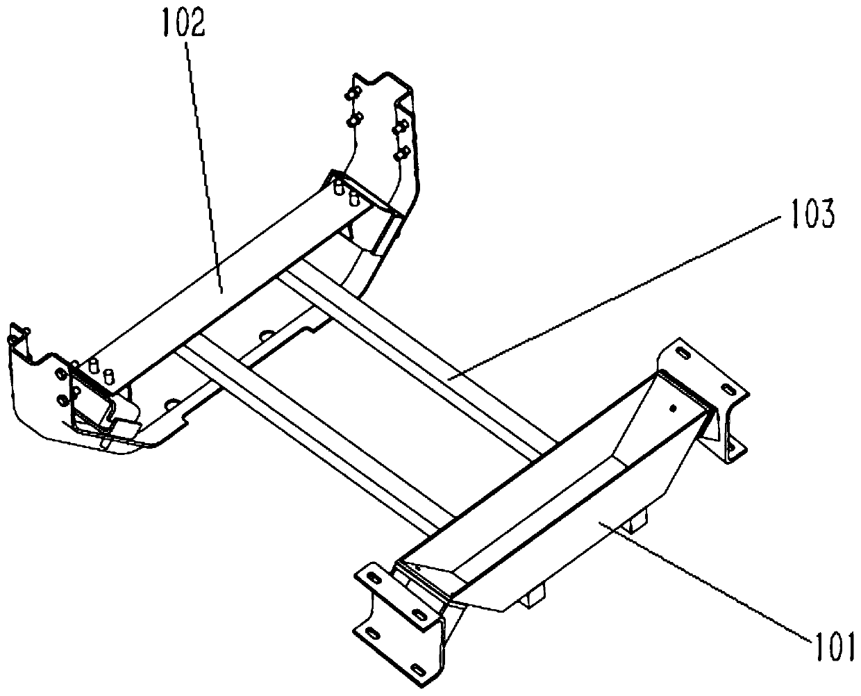
[0040] Please refer to figure 1 , this embodiment discloses a mold for engine installation, including a first installation part, a second installation part and a connecting rod connecting the first installation part and the second installation part, the two ends of the first installation part are respectively used It is used to connect the two front suspension lower brackets of the engine, and the two ends of the second mounting part are respectively used to connect the two rear suspension brackets;

[0041] Wherein, the first installation part is a hollow structure, and the second installation part is a plate structure; specifically, the first installation part is box-shaped, and an opening is provided on the top side of the first installation part. The setting of the first installation part is box-shaped, so that the first installation part can cooperate with the front suspension beam 12 of the engine. It can be understood that the front suspension beam 12 of the engine is a...

Embodiment 2

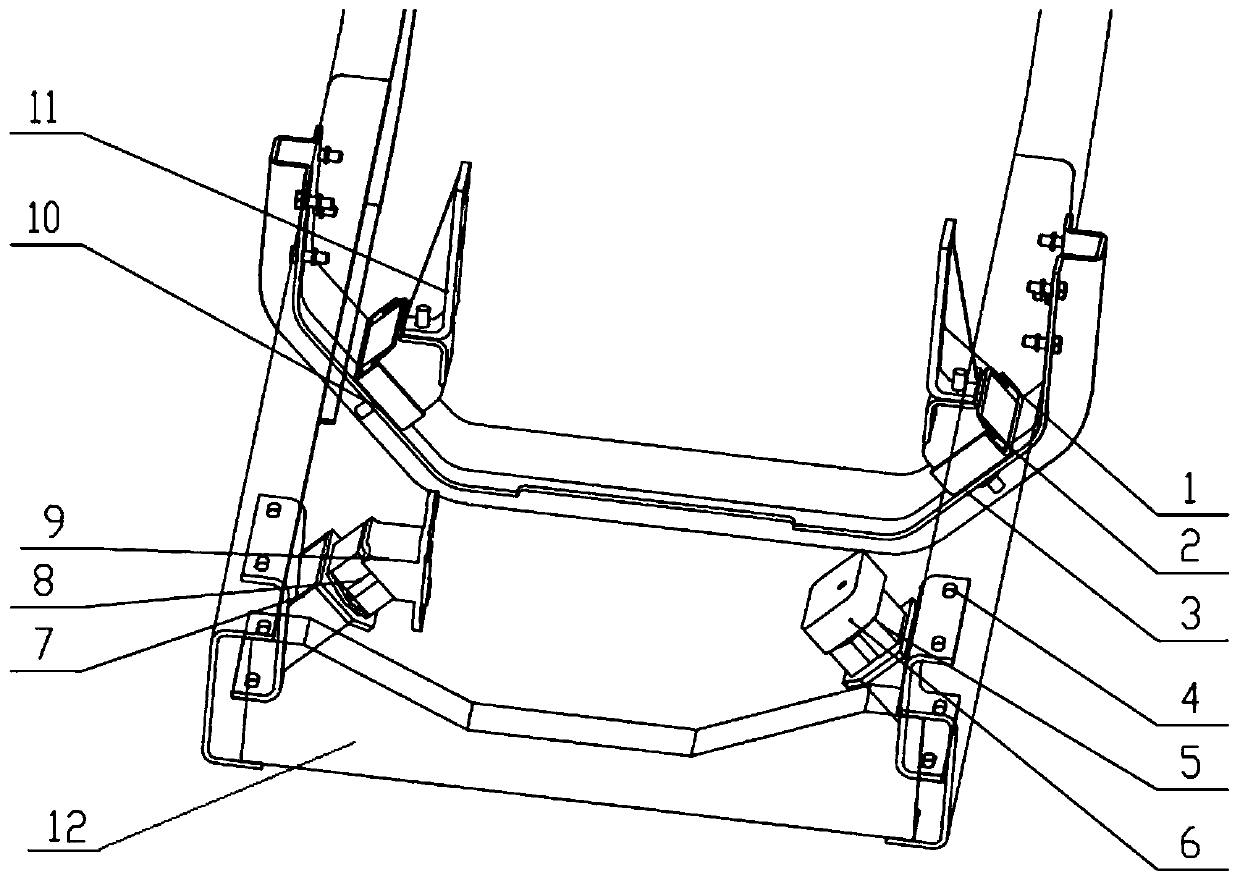
[0047] First of all, please refer to the figure 2, the engine to be installed in embodiment 2 is a part of the engine, which includes a fixed ring beam 3, the first position of the ring beam 3 is installed with the front suspension beam 12, and the second position of the ring beam 3 is installed with the rear suspension beam 10; the front suspension beam 12 The two sides need to be separately bottled to connect the first front suspension lower bracket 4 and the second front suspension lower bracket 7, the first front suspension lower bracket 4 and the second front suspension lower bracket 7 are collectively called the front suspension lower bracket, the first front suspension lower bracket The lower bracket 4 is connected to the first front suspension upper bracket 6, the second front suspension lower bracket 7 is connected to the second front suspension upper bracket 9, and the first front suspension upper bracket 6 and the second front suspension upper bracket 9 are collecti...


PUM


Abstract

The invention discloses a clamping fixture for engine installation and an engine installation method. The clamping fixture comprises a first mounting part, a second mounting part and a connecting rodfor connecting the first mounting part and the second mounting part, the two ends of the first mounting part are used for being connected with two front overhang lower supports of an engine respectively, and the two ends of the second mounting part are used for being connected with two rear overhang supports respectively. The first mounting part is of a hollow structure, and the second mounting part is of a plate-shaped structure. Aiming at the characteristics of the engine shell, the existing mounting method is improved, so that the engine can be successfully mounted at one time.

Description

technical field [0001] The invention relates to the field of vehicle manufacturing, in particular to a mold for engine installation and an engine installation method. Background technique [0002] Engine installation mainly refers to the installation of the engine suspension system. The engine suspension system includes the suspension upper bracket, the suspension lower bracket and the shock-absorbing cushion. The main functions of the suspension system are vibration isolation, engine support and positioning, engine protection, overcoming and balancing the reaction force generated by torque output. [0003] The inventor believes that at present, due to the poor precision of the parts, there are long holes in the left and right and front and rear directions of the suspended upper bracket and the suspended lower bracket, which leads to the lack of positioning of the engine, and the workshop is in the process of construction. There are problems with construction difficulties, ...

Claims


Application Information

Patent Timeline
Patent Type & Authority Applications(China)
IPC IPC(8): B62D65/02B62D65/04
CPCB62D65/024B62D65/04
Inventor 于文尚杨彦三孟国庆邢占斌周后昌王攀
Owner ZHONGTONG BUS HLDG
Why Eureka
Try Eureka