
Garbage compressing and packaging integrated machine

A technology of garbage compression and integrated machine, which is applied in the direction of press, garbage conveying, garbage collection, etc., can solve the problems of high compression stability, inability to pack garbage, etc., so as to reduce the occupied area, be less prone to failure, and reduce garbage removal and transportation. the effect of the number of times

Active Publication Date: 2020-03-24
JIANGSU QINGSHI TECH
View PDF21 Cites 1 Cited by
  • Summary
  • Abstract
  • Description
  • Claims
  • Application Information

AI Technical Summary

Problems solved by technology

[0004] Although the device can solve the problem of increasing the loading rate of the box, it cannot pack the garbage, and the overall compression stability is high. Therefore, we propose a garbage compression and packaging machine

Method used


Image

  • Garbage compressing and packaging integrated machine
  • Garbage compressing and packaging integrated machine
  • Garbage compressing and packaging integrated machine

Examples


Embodiment 1

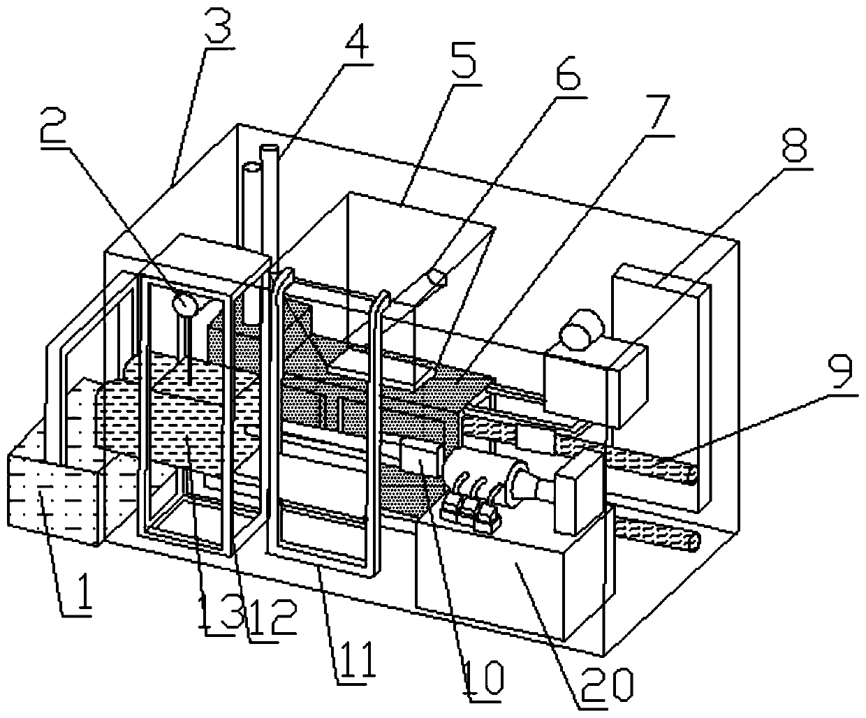
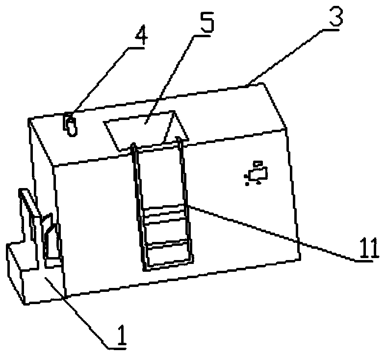
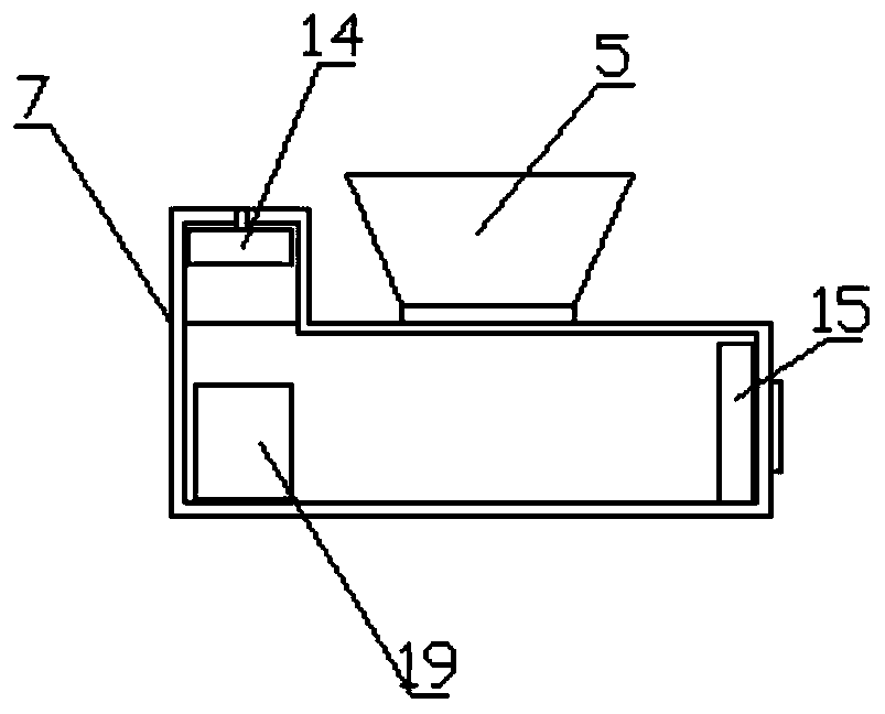
[0026] Such as Figure 1-5 As shown, a garbage compression and packaging machine includes a casing 3, a baler 1 and a compression box 7, one side of the casing 3 is provided with a hoist 11 through a mounting frame, and one end of the casing 3 is connected by a bolt A baler 1 is installed, and a compression box 7 is installed through bolts in the casing 3, and a discharge hydraulic cylinder 6 is installed on one side of the compression box 7 through a mounting seat, and one end of the compression box 7 is set through a fixing seat There is a horizontal hydraulic cylinder 9, one end of the compression box 7 is equipped with a discharge lifting frame 12 through a bolt, and the inner top of the discharge lifting frame 12 is provided with a hoist 2 through a limit plate, and the lower end of the hoist 2 is provided with a discharge Material box 13, the inner side of the bracket of the discharge lifting frame 12 is embedded with a slide groove 16 through screws, and the two ends of...

Embodiment 2

[0038] Such as Figure 1-5As shown, a garbage compression and packaging machine includes a casing 3, a baler 1 and a compression box 7, one side of the casing 3 is provided with a hoist 11 through a mounting frame, and one end of the casing 3 is connected by a bolt A baler 1 is installed, and a compression box 7 is installed through bolts in the casing 3, and a discharge hydraulic cylinder 6 is installed on one side of the compression box 7 through a mounting seat, and one end of the compression box 7 is set through a fixing seat There is a horizontal hydraulic cylinder 9, one end of the compression box 7 is equipped with a discharge lifting frame 12 through a bolt, and the inner top of the discharge lifting frame 12 is provided with a hoist 2 through a limit plate, and the lower end of the hoist 2 is provided with a discharge Material box 13, the inner side of the bracket of the discharge lifting frame 12 is embedded with a slide groove 16 through screws, and the two ends of ...


PUM


Abstract

The invention discloses a garbage compressing and packaging integrated machine. The machine comprises a machine shell, a packaging machine and a compressing box. One side of the machine shell is provided with a lifting machine through a mounting frame, one end of the machine shell is provided with the packaging machine through a bolt, the compressing box is mounted in the machine shell through a bolt, one side of the compressing box is provided with a discharging hydraulic oil cylinder through a mounting base, one end of the compressing box is provided with a transverse hydraulic oil cylinderthrough a fixed base, one end of the compressing box is provided with a discharging lifting frame through a bolt, a winch is arranged on the inner top end of the discharging lifting frame through a limiting plate, a discharging box is arranged on the lower end of the winch, a sliding groove is embedded in the inner side of a support of the discharging lifting frame through a screw, sliding blocksare arranged on the two ends of the discharging box, and the sliding blocks are located in the sliding groove. The garbage compressing and packaging integrated machine is diverse in function, easy tooperate, and convenient to produce, capable of meeting multiple needs in use, and suitable for being widely used.

Description

technical field [0001] The invention relates to the technical field of garbage disposal, in particular to an integrated machine for compressing and packing garbage. Background technique [0002] The garbage compactor is one of the main equipments to achieve garbage compression and volume reduction, and it is also the main processing equipment of the garbage transfer station. The garbage compressor is the main equipment of the garbage transfer station. It is a machine controlled by the hydraulic system to compress the collected garbage to reduce the volume of the garbage. [0003] Patent No. CN201821540851.5 discloses a garbage compressor that enters the sewage storage space through a filter structure, and at the same time separates the compressed garbage and sewage to avoid high-pressure water and reduce the possibility of sewage leakage; Extrusion, the reduction of water content in garbage is beneficial to improve the loading rate of the box. [0004] Although this device...

Claims


Application Information

Patent Timeline
IPC IPC(8): B65F9/00B30B9/30B30B15/00
CPCB65F9/00B30B9/30B30B9/301B30B15/00
Inventor 万仁军
Owner JIANGSU QINGSHI TECH
Learn More