
Roadbed and method for controlling differential settlement of road-bridge transition section of high-speed railway

A technology for high-speed railways and transition sections, which is applied in the field of foundation treatment and high-speed railway subgrades. It can solve problems such as difficulty in rolling subgrade fillers in place, shortage of graded crushed stone materials, and increased foundation settlement, so as to increase driving safety, Good self-compactness and small foundation disturbance

Active Publication Date: 2020-03-24
TONGJI UNIV
View PDF9 Cites 5 Cited by
  • Summary
  • Abstract
  • Description
  • Claims
  • Application Information

AI Technical Summary

Problems solved by technology

Although the problem of large differential settlement between the transition sections of roads and bridges has been alleviated to a certain extent, there are still some disadvantages, such as the shortage of graded crushed stone materials, the use of graded crushed stones mixed with cement materials requires a large amount of materials, and the self-weight of the roadbed increases. The settlement caused by the foundation increases; when the transitional slab is used and the subgrade is not properly treated, the settlement of the subgrade will cause the slab to be voided, or even cause the slab to break; due to the special position of the transition section of the road and bridge, the subgrade filling is difficult to roll In place, resulting in low compaction of the packing behind the abutment, resulting in differential settlement

Method used


Image

  • Roadbed and method for controlling differential settlement of road-bridge transition section of high-speed railway
  • Roadbed and method for controlling differential settlement of road-bridge transition section of high-speed railway
  • Roadbed and method for controlling differential settlement of road-bridge transition section of high-speed railway

Examples


Embodiment

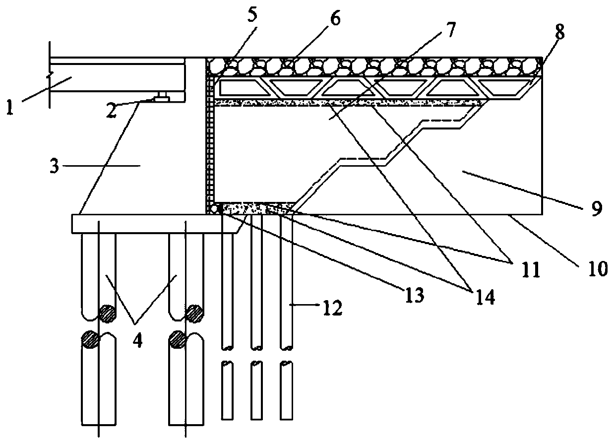
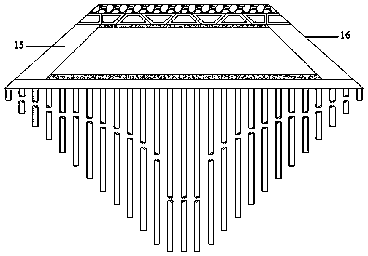
[0035] like figure 1 As shown, the present invention provides a subgrade for controlling the uneven settlement of the transition section of a high-speed railway road and bridge, including a subgrade body 9 and a transition subgrade arranged between the subgrade body 9 and the bridge abutment 3. The subgrade surface layer 6 is laid above the transition subgrade, and the bottom There are foundation reinforcement piles 12 arranged in the horizontal and vertical directions and extending into the underground soil layer.

[0036] The transition roadbed comprises a trapezoidal reinforced concrete body 8, a first foamed concrete body 7 and a second foamed concrete body 14 respectively laid on the upper top surface and the lower bottom surface of the first foamed concrete body 7, and the trapezoidal reinforced concrete body 8 is arranged on the first foamed concrete body 14. On top of the second foamed concrete body 14 on the top surface of the body 7 , the first foamed concrete body 7...


PUM

PropertyMeasurementUnit
Thicknessaaaaaaaaaa
Thicknessaaaaaaaaaa
Diameteraaaaaaaaaa

Abstract

The invention relates to a roadbed for controlling differential settlement of a road-bridge transition section of a high-speed railway. The roadbed comprises a roadbed body and a transition roadbed arranged between the roadbed body and a bridge abutment, a roadbed surface layer is paved above the transition roadbed; foundation reinforcing piles which are arranged in the transverse direction and the longitudinal direction and extend into an underground soil layer are arranged below the transition roadbed . The lengths of the foundation reinforcing piles are sequentially reduced from the centerline of the roadbed to two sides; the transition roadbed comprises a first foam concrete body and second foam concrete bodies laid on the top face and the bottom face of the first foam concrete body respectively. A layer of trapezoidal reinforced concrete body is also arranged between the top surface of the first foam concrete body and the second foam concrete body; the first foam concrete body and the trapezoidal reinforced concrete body are matched with each other to form a contact transition surface with a stepped structure with the roadbed body. Compared with the prior art, the roadbed hasthe advantages that differential settlement of a road and bridge transition section is controlled, construction is convenient, and the like.

Description

technical field [0001] The invention relates to the technical field of high-speed railway subgrade and ground treatment, in particular to a subgrade and a method for controlling uneven settlement of a transition section of a high-speed railway road and bridge. Background technique [0002] In the field of transportation engineering, in order to pursue the safety, comfort and stability of high-speed railway trains, there are high requirements for the smoothness of the track. The high-speed railway road-bridge transition section is a special section connecting the subgrade structures. It bears the static and dynamic loads of the track structure and high-speed trains. Due to the difference in settlement and stiffness between the subgrade and the abutment, it is inevitable that the transition section of the road and bridge is not properly controlled. It will cause unevenness and bending angles on the rail surface, which will affect the comfort of passengers and even have potenti...

Claims


Application Information

Patent Timeline
IPC IPC(8): E01B2/00E01C3/04E01C3/00
CPCE01B2/00E01C3/00E01C3/04
Inventor 周顺华王炳龙王长丹马文杰刘琤玉
Owner TONGJI UNIV
Learn More