Blasting dust decreasing device for building construction

A dust suppression device and construction technology, applied in the direction of blasting, liquid separation agent, dispersed particle separation, etc., can solve the problems of debris splashing, device damage, debris and device collision, etc., to improve stability, facilitate fixing, The effect of increasing friction

Inactive Publication Date: 2020-03-24
刘岩岩
View PDF1 Cites 6 Cited by
  • Summary
  • Abstract
  • Description
  • Claims
  • Application Information

AI Technical Summary

Problems solved by technology

An open-air blasting directional shielding dust suppression device in the above-mentioned patent has the following disadvantages: when the existing device performs dust reduction treatment on dust, due to the impact force during blasting, debris may be splashed, which may make the debris Collision between swarf and the device, causing damage to the device

Method used


Image

  • Blasting dust decreasing device for building construction
  • Blasting dust decreasing device for building construction
  • Blasting dust decreasing device for building construction

Examples


Embodiment 1

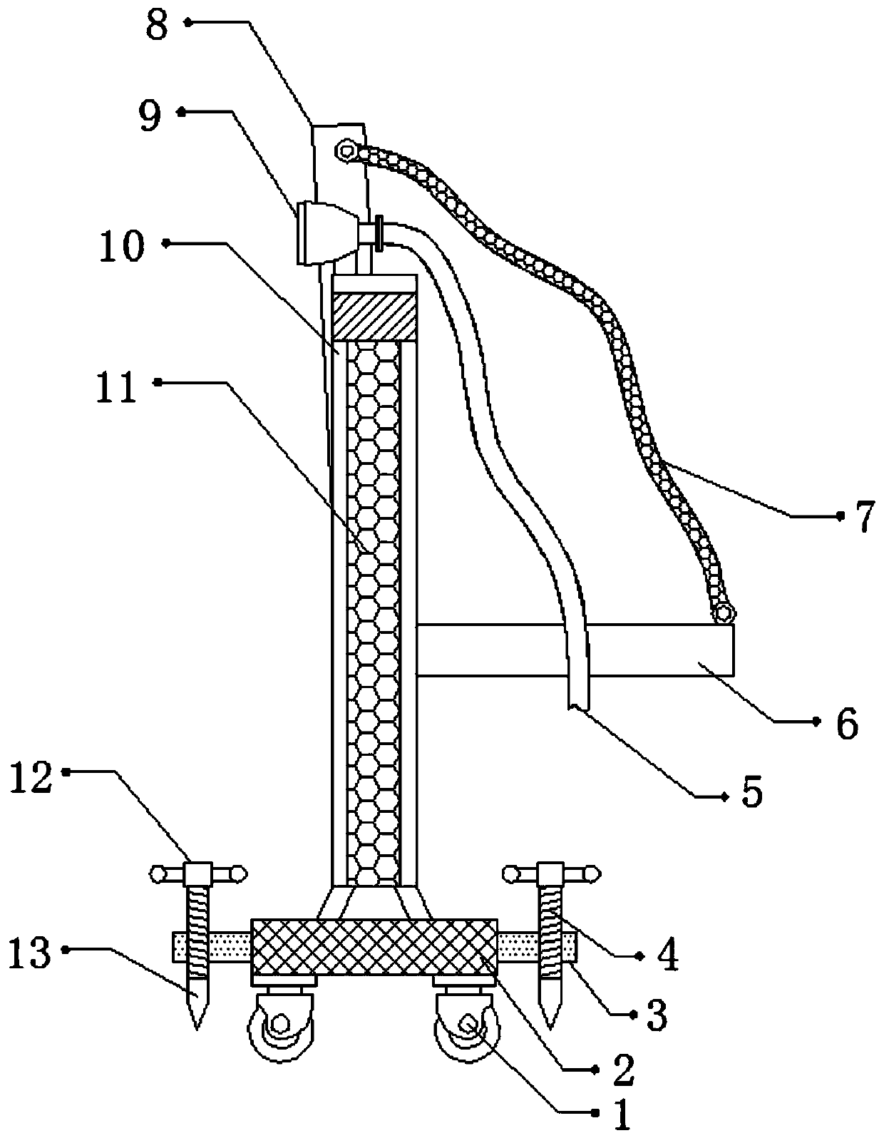
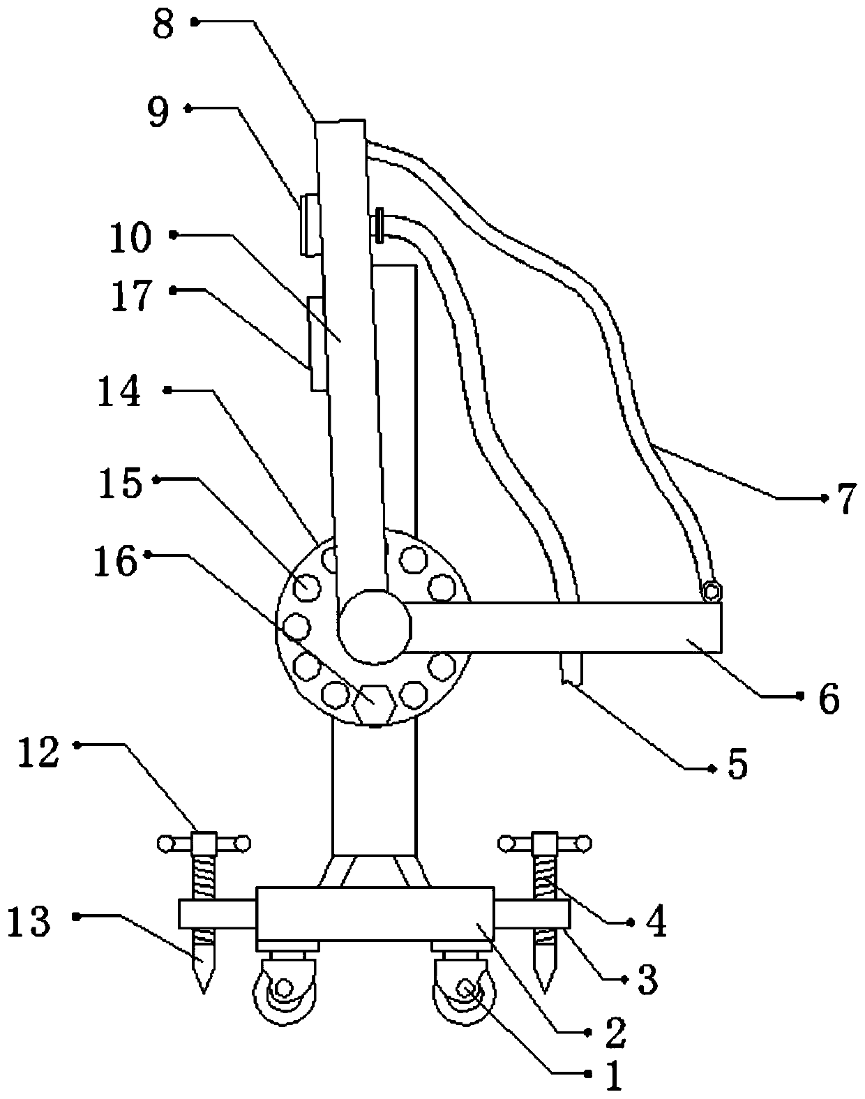
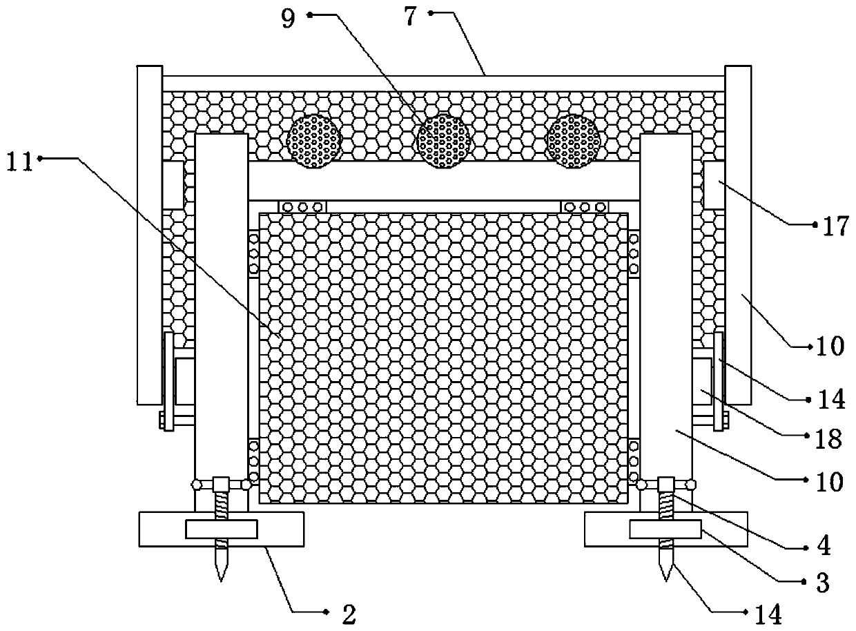
[0027] refer to Figure 1-4 , a blasting dust suppression device for building construction, comprising two fixed seats 2, the top outer walls of the two fixed seats 2 are connected with a fixed frame 10 by bolts, and the inner wall of the fixed frame 10 is connected with a steel wire mesh 11 through a hinge, the fixed frame The outer walls on both sides of 10 are connected with fixed plates 6 by bolts, and the outer walls of one side of the two fixed plates 6 are connected with damping bearings 18 by bolts, and the inner walls of the two damping bearings 18 are all rotatably connected with rotating shafts, and the two One side outer wall of the rotating shaft is connected with a rotating rod 8 by bolts, and the opposite side outer walls of the two rotating rods 8 are connected with a protective net 7 by bolts, and the top inner wall of the fixed frame 10 is connected with a support seat by bolts, and The top outer wall of the support seat is connected with an atomizing nozzle ...

Embodiment 2

[0035] refer to Figure 5 , a blasting dust suppression device for building construction. Compared with Embodiment 1, the outer walls of the bottom of the two fixing seats 2 are provided with U-shaped grooves 22, and the top inner walls of the two U-shaped grooves 22 are connected by bolts. There are hydraulic rods 19, the bottom outer walls of the two hydraulic rods 19 are connected with support plates 21 by bolts, and the bottom outer walls of the two support plates 21 are provided with a plurality of fixed teeth 20 distributed equidistantly.

[0036] Working principle: when in use, the device is moved to a suitable position through the moving wheel 1. After the movement is completed, the handle 12 is turned to make the threaded rod 4 drive the insertion rod 13 to rotate, so that the insertion rod 13 is inserted into the soil for convenience. Fix the device to prevent the device from falling due to the impact force generated during blasting and thus affect the dust fall. The...


PUM


Abstract

The invention discloses a blasting dust decreasing device for building construction. The blasting dust decreasing device comprises two fixing seats. Fixing frames are fixed to the outer walls of the tops of the two fixing seats, and a steel wire net is connected to the inner walls of the fixing frames in a hinged manner. Fixing plates are fixed to the outer walls of the two sides of the fixing frames, and damping bearings are fixed to the outer walls of one sides of the two fixing plates. Rotating shafts are rotationally connected to the inner walls of the two damping bearings, and rotating rods are fixed to the outer walls of one sides of the two rotating shafts. A protection net is fixed between the outer walls of the opposite sides of the two rotating rods, and a supporting seat is fixed to the inner walls of the tops of the fixing frames. By means of the blasting dust decreasing device for building construction, the phenomenon that the ascending speed of dust is high due to the acting force generated during blasting, and dust decreasing is affected can be avoided; the phenomenon that the device falls due to the impact force generated during blasting, and dust decreasing is affected can be prevented; and the phenomenon that the device falls, and dust decreasing is affected can be prevented.

Description

technical field [0001] The invention relates to the technical field of building construction, in particular to a blasting dust suppression device for building construction. Background technique [0002] When carrying out blasting operations on an open-air construction site, water mist is usually generated by a dust sprayer. When the water mist comes into contact with dust floating in the air, it is absorbed by the dust, increasing the proportion of dust, inhibiting the flow of dust in the air, and accelerating the blasting process. The dust settles to realize the purification of the air, so as to achieve the purpose of easy operation. [0003] After retrieval, the Chinese patent authorization number is CN209541589U, which discloses a directional shielding dust suppression device for open-air blasting, including a fixed bracket group and a protective plate group. The fixed bracket group includes a bracket base, a main bracket rod and a top support seat, and a protective plate...

Claims


Application Information

Patent Timeline
Patent Type & Authority Applications(China)
IPC IPC(8): F42D1/00F42D3/04B01D47/06
CPCB01D47/06F42D1/00F42D3/04
Inventor 刘岩岩
Owner 刘岩岩
Why Eureka
Try Eureka