ZnO varistor-based fault discharge device and control method thereof

A varistor and current bleed technology, applied in the power grid field, can solve the problems of loss of bleeder function, influence of line overcurrent protection, poor current carrying capacity, etc., so as to cope with short-circuit impulse current, reduce protection cost, and avoid secondary influence. Effect

Active Publication Date: 2020-03-24
HUNAN UNIV
View PDF5 Cites 4 Cited by
  • Summary
  • Abstract
  • Description
  • Claims
  • Application Information

AI Technical Summary

Problems solved by technology

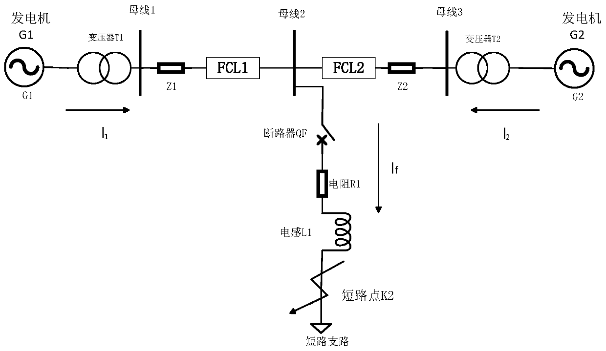
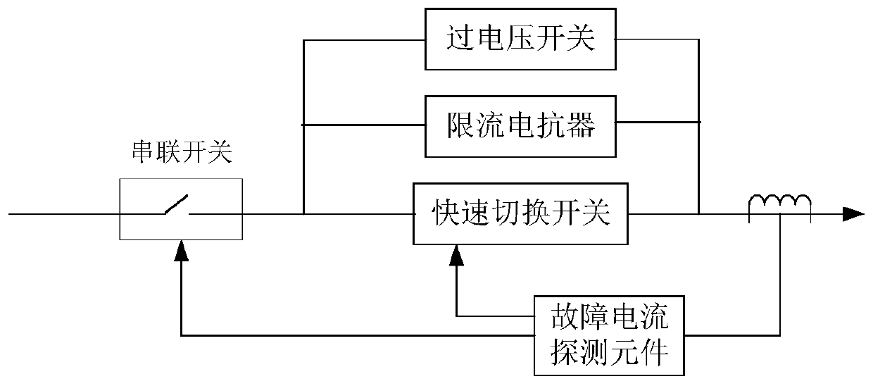
[0006] 1) There is a certain loss in the series connection of FCL in the power grid, and the power consumption caused by a large number of distributed series connection in the power grid will increase with the increase of the number;
[0007] 2) The cost of new materials such as superconducting FCL is relatively high, and the economy is poor;
[0008] 3) Electronic devices in power electronic FCL have low withstand voltage level and poor stability;
[0009] 4) The current-limiting reactance of FCL is connected in series to the line to suppress the short-circuit current, but because the dynamic impedance characteristics of the line are changed, that is, the equivalent electrical distance of the line before and after the fault changes

Method used


Image

  • ZnO varistor-based fault discharge device and control method thereof
  • ZnO varistor-based fault discharge device and control method thereof
  • ZnO varistor-based fault discharge device and control method thereof

Examples


Embodiment 1

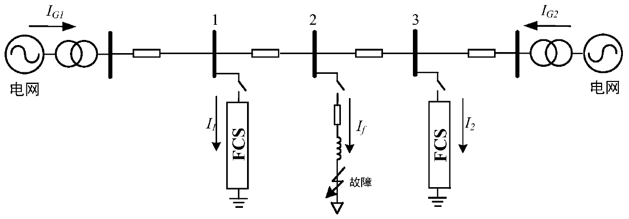
[0043] Figure 5 It is a structural schematic diagram of a ZnO varistor-based fault leakage device according to an embodiment of the present invention.

[0044] Such as Figure 5 As shown, the fault leakage device based on ZnO varistor includes: a current transformer 10 , a signal processor 20 , a fault leakage device 30 and a controller 40 .

[0045] Among them, see Figure 5 , the current transformer 10 is arranged at the front end of the circuit breaker QS in the transmission line, and is used to detect the current in the transmission line. The signal processor 20 is connected with the current transformer 10, and is used for converting the detection signal of the current transformer 10 from an analog signal to a digital signal. The fault bleeder 30 includes a main bleed passage 31 and a plurality of secondary bleed passages 32 ( Figure 5 n secondary leakage paths 32 are shown in ), the main leakage path 31 includes a first fast switch S0 and at least one ZnO varistor ...

Embodiment 2

[0058] Figure 6 It is a flow chart of the control method of the fault leakage device according to the embodiment of the present invention.

[0059] In this embodiment, the control method of the fault leakage device is used for the above-mentioned fault leakage device based on ZnO varistor, such as Figure 6 As shown, the method includes the following steps:

[0060] S1, to obtain the current in the transmission line.

[0061] S2, judging whether the current in the transmission line is greater than the rated breaking current of the circuit breaker.

[0062] S3. If the current in the transmission line is greater than the rated breaking current of the circuit breaker, control the first fast switch to close.

[0063] S4, obtaining the current in the transmission line again.

[0064] S5, judging whether the current in the transmission line is still greater than the rated breaking current of the circuit breaker.

[0065] S6. If the current in the transmission line is still gre...


PUM


Abstract

The invention discloses a ZnO varistor-based fault discharge device and a control method thereof, and the fault discharge device comprises a current transformer which is used for detecting a current in a power transmission line; a signal processor which is used for processing the current detection signal; a fault bleeder which comprises a main bleeder path and a plurality of secondary bleeder paths, the main bleeder path comprises a first quick switch and at least one ZnO piezoresistor which are connected in series, and each secondary bleeder path comprises a second quick switch and a bleederresistor which are connected in series; and a controller which is used for carrying out closing control on the first quick switch and/or each second quick switch when the current in the power transmission line is greater than the rated breaking current of the circuit breaker, so that the current of the power transmission line is less than or equal to the rated breaking current of the circuit breaker, and controlling the closed quick switch to be disconnected after the circuit breaker is disconnected. The fault discharge device can reduce the protection cost of the power grid fault and improvethe protection effect of the power grid fault on the premise of not influencing the normal operation of the power grid.

Description

technical field [0001] The invention relates to the technical field of power grids, in particular to a ZnO varistor-based fault leakage device and a control method thereof. Background technique [0002] The scale of my country's power grid continues to expand, the structure of the power grid is gradually strengthened, the application of low-impedance and large-capacity transformers in the power grid continues to increase, the capacity of single machines in the system, the capacity of power plants, and the load and load density continue to increase. The operation of the unit and the construction of the UHV transmission backbone grid have greatly improved the power transmission capacity of the main grid and enhanced the safety and reliability of the grid operation. At the same time, it has also led to a sharp increase in the short-circuit current level of each important node. When the short-circuit current occurs, the current value increases instantaneously, which is several ti...

Claims


Application Information

Patent Timeline
IPC IPC(8): H02H9/02H02H7/26
CPCH02H7/26H02H9/02
Inventor 李宁刘绪斌黎灿兵周斌汪鑫
Owner HUNAN UNIV
Why Eureka
Try Eureka