Synchronous rectification control method and device for phase-shifted full-bridge/push-pull bidirectional converter

A bidirectional converter and synchronous rectification technology, which is applied in the direction of output power conversion device, conversion of AC power input to DC power output, high-efficiency power electronic conversion, etc., can solve the problem of low efficiency at light load, reduce driving loss, reduce Effects of system noise and drive time reduction

Active Publication Date: 2020-03-24
BEIJING MECHANICAL EQUIP INST
View PDF6 Cites 4 Cited by
  • Summary
  • Abstract
  • Description
  • Claims
  • Application Information

AI Technical Summary

Problems solved by technology

[0003] In view of the above-mentioned analysis, the present invention aims to provide a synchronous rectification control method and device for a phase-shifted full-bridge / push-pull bidirectional converter, to solve the drive mode of taking or logic of the full-bridge phase-shifted drive signal in the prior art The problem of low light load efficiency caused by buck mode

Method used


Image

  • Synchronous rectification control method and device for phase-shifted full-bridge/push-pull bidirectional converter
  • Synchronous rectification control method and device for phase-shifted full-bridge/push-pull bidirectional converter
  • Synchronous rectification control method and device for phase-shifted full-bridge/push-pull bidirectional converter

Examples


Embodiment Construction

[0044] Preferred embodiments of the present invention will be described in detail below in conjunction with the accompanying drawings, wherein the accompanying drawings constitute a part of the application and together with the embodiments of the present invention are used to explain the principle of the present invention and are not intended to limit the scope of the present invention.

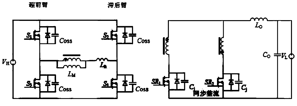
[0045] Figure 1 is a circuit topology diagram of a typical phase-shifted full-bridge / push-pull bidirectional converter; 1 , Super forearm lower arm switch S 3 , Lagging arm upper bridge arm switch S 2 , switch S of the lower arm of the lagging arm 4 , Exciting inductance L M , resonant inductance L lk ; Among them, the switch S 1 , S 3 After series connection with the primary power supply V H parallel, switch S 2 , S 4 Also connected in series with the power supply V H Parallel connection; excitation inductance L M It is connected in parallel with the primary coil of the transformer...


PUM


Abstract

The invention relates to a synchronous rectification control method and device for a phase-shifted full-bridge/push-pull bidirectional converter, belongs to the technical field of converter rectification control, and solves the problem of low light load efficiency in a buck mode caused by an OR logic driving mode of a full-bridge phase-shifted driving signal in the prior art. A primary side circuit of the bidirectional converter comprises a leading arm upper bridge arm switch S1, a leading arm lower bridge arm switch S3, a lagging arm upper bridge arm switch S2 and a lagging arm lower bridge arm switch S4. The secondary side circuit comprises a first synchronous rectification switch SR1 connected with the synonym end of the secondary side winding and a second synchronous rectification switch SR2 connected with the dotted end of the secondary side winding; the method comprises the steps that when the bidirectional converter works in a buck mode, driving levels of switches S1-S4 are received, AND logic operation is carried out on the driving levels of the switches S1 and S4, and a driving level of a switch SR1 is generated; and performing AND logic operation on the driving levels ofthe switch S2 and the switch S3 to generate a driving level of the switch SR2. And the efficiency problem of the converter under light load is improved.

Description

technical field [0001] The invention relates to the technical field of converter rectification control, in particular to a synchronous rectification control method and device for a phase-shifted full-bridge / push-pull bidirectional converter. Background technique [0002] When using the phase-shifted full-bridge / push-pull bidirectional converter topology, when the bidirectional converter works in the step-down mode, the high-voltage side full-bridge switch works in the phase-shifted control mode, and the full-wave rectification on the low-voltage side is under greater load. The current stress of the rectification system can reduce the power loss of the rectification unit by using the synchronous rectification method. The traditional synchronous rectification method is usually driven by the full-bridge phase-shift drive signal or logic method, and is widely used in the full-bridge analog control chip. When the converter is under light load condition, excessive driving time wil...

Claims


Application Information

Patent Timeline
Patent Type & Authority Applications(China)
IPC IPC(8): H02M7/219H02M1/088
CPCH02M1/088H02M7/219Y02B70/10
Inventor 刘博禹王浩宇郭鑫张斌
Owner BEIJING MECHANICAL EQUIP INST
Why Eureka
Try Eureka