Air hammer for steel piece forging and stamping

An air hammer and forging technology, applied in forging/pressing/hammer devices, forging/pressing/hammering machines, power hammers, etc., can solve the problem of inability to accurately adjust the position of the workpiece to be processed and the positional deviation of the air hammer. , low forging quality of workpieces to be processed, etc., to achieve the effect of improving processing quality, improving processing efficiency and high practicability

Active Publication Date: 2020-03-27
苏州乾元机械配件有限公司
View PDF6 Cites 1 Cited by
  • Summary
  • Abstract
  • Description
  • Claims
  • Application Information

AI Technical Summary

Problems solved by technology

[0004] The above existing technical solutions have the following defects: Since the workpiece to be processed needs to be pressed repeatedly by the hammer head of the air hammer, and the different end faces of the workpiece to be processed and the position of each end face have different processing requirements, it is difficult for the operator to , when the workpiece to be processed is turned over or moved, the position of the workpiece to be processed cannot be adjusted accurately, and then the position of the hammer head of the air hammer is deviated, resulting in a large number of workpieces to be processed with low forging quality, and finally they can only be discarded, wasting costs

Method used


Image

  • Air hammer for steel piece forging and stamping
  • Air hammer for steel piece forging and stamping
  • Air hammer for steel piece forging and stamping

Examples


Embodiment Construction

[0036] The present invention will be described in further detail below in conjunction with the accompanying drawings.

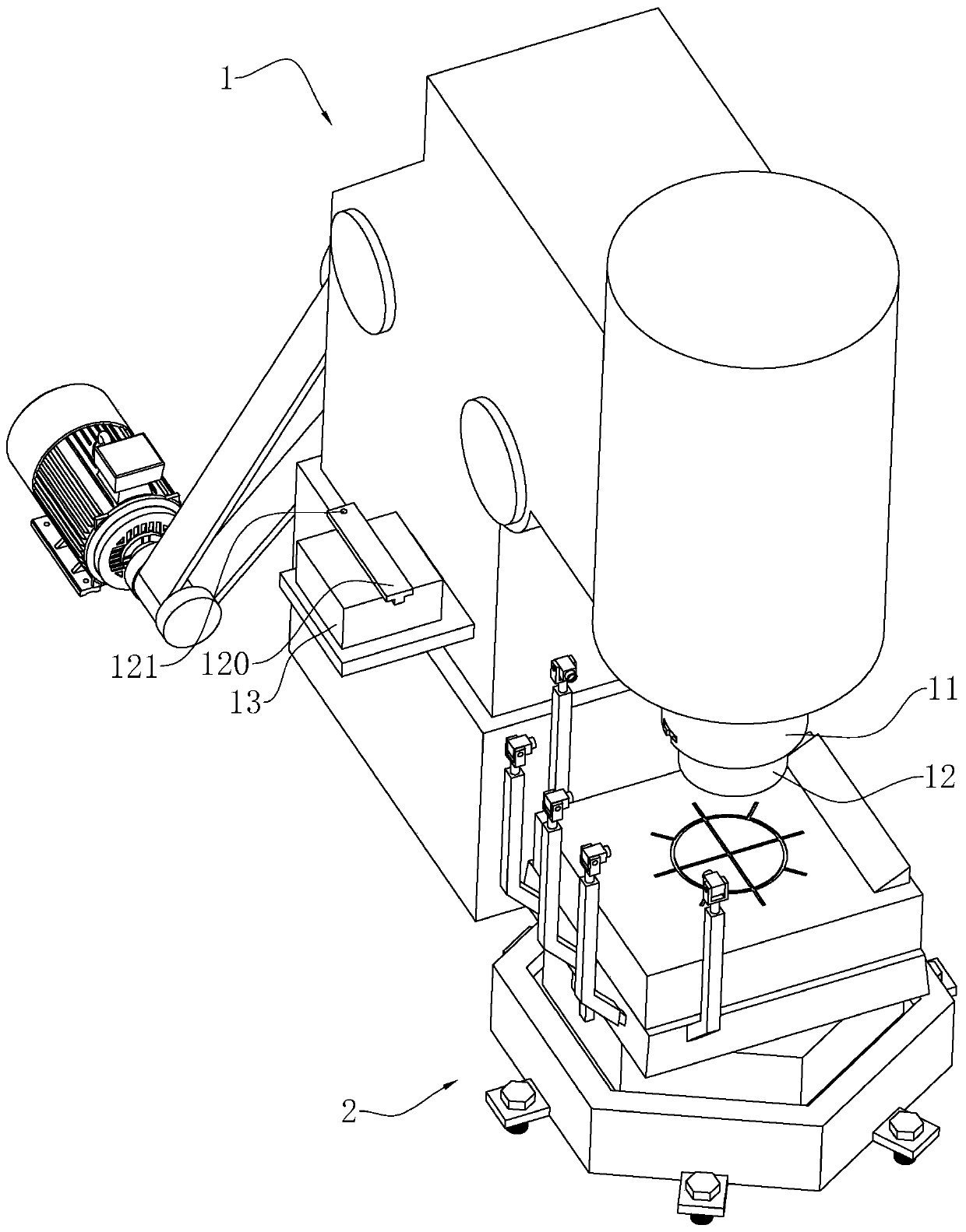
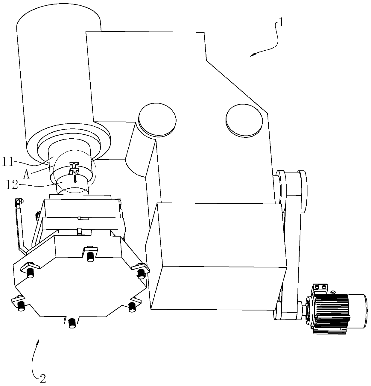
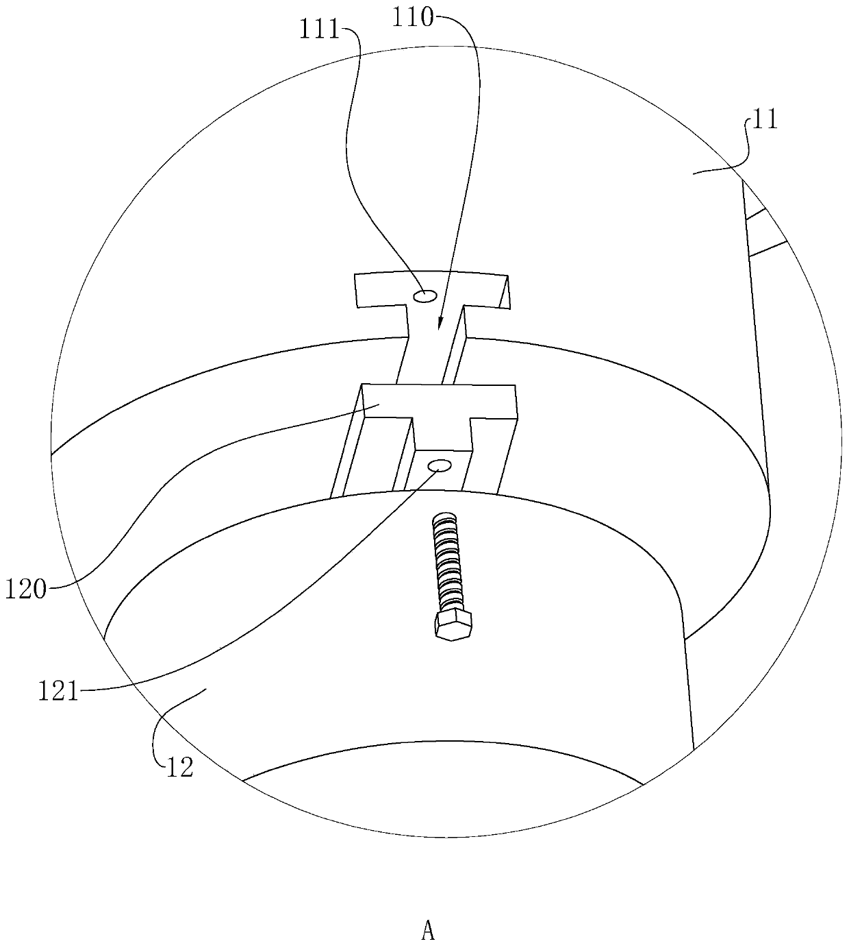
[0037] refer to figure 1 , is an air hammer for steel forging disclosed by the present invention, including air hammer body 1, air hammer body 1 includes motor, crankshaft, gear shaft, connecting rod, piston, down-swing valve, compression cylinder, and up-swing valve , working cylinder, hammer column 11 and hammer head 12, the motor is exposed to the outside world, the motor provides power for the air hammer, and the motor is decelerated by the pulley and gear two-stage reduction mechanism, driving the crankshaft and connecting rod to drive the piston to do linear reciprocation up and down in the compression cylinder Movement, the upper and lower chambers of the compression cylinder respectively form pressure air, which is input into the upper and lower chambers of the working cylinder through the upper and lower rotary valves. The working cylinder is vertica...


PUM


Abstract

The invention discloses an air hammer for steel piece forging and stamping, and relates to the field of air hammers. The problems that an operator cannot easily adjust the position of a to-be-machinedworkpiece accurately, thus, deviation of the pounding and stamping position of a hammer head occurs, and the to-be-machined workpiece is low in machining quality and prone to being wasted are solved.According to the technical scheme, the air hammer comprises an air hammer body, the air hammer body is internally provided with a hammer column, and the lower end of the hammer column is detachably connected with a hammer head; an anvil block is arranged below the hammer head, and the upper surface of the anvil block is provided with a scale groove; the shape formed by the scale groove is the same with the shape of the cross section of the hammer head, the middle of the shape formed by the scale groove is provided with a cross-shaped auxiliary groove, and the periphery of the scale groove isprovided with a plurality of mark grooves; the vertical side surface of the anvil block is provided with a main irradiation lamp and a plurality of auxiliary irradiation lamps; and the air hammer hasthe technical effects that an operator determines the position where the to-be-machined workpiece should be located through prompting of the scale groove, the auxiliary groove, the mark grooves, the main irradiation lamp and the auxiliary irradiation lamps, so that the pounding and stamping position is not prone to deviating, and the rejection rate is decreased.

Description

technical field [0001] The invention relates to the technical field of air hammers, in particular to an air hammer used for steel forging. Background technique [0002] At present, the application range of the valve is very wide, and it is a common device in life. A valve is a device used to control the direction, pressure, and flow of a fluid in a fluid system. It is a device that makes the medium (such as liquid, gas, powdery solid) in the piping and equipment flow or stops and controls its flow. The valve body is a major part of the valve, and the quality of the valve body is one of the main factors affecting the quality of the valve. In the production process of the valve body with medium and high pressure specifications, forging is mainly used to process the valve body. Pneumatic hammer is a kind of free forging equipment, which is frequently used in small and medium-sized enterprises. [0003] The existing notification number is the invention patent of CN106607535B,...

Claims


Application Information

Patent Timeline
Patent Type & Authority Applications(China)
IPC IPC(8): B21J7/04B21J13/06B21J13/08F16F15/02
CPCB21J7/04B21J13/06B21J13/085F16F15/02
Inventor 周建民徐赟王雪芬
Owner 苏州乾元机械配件有限公司
Why Eureka
Try Eureka