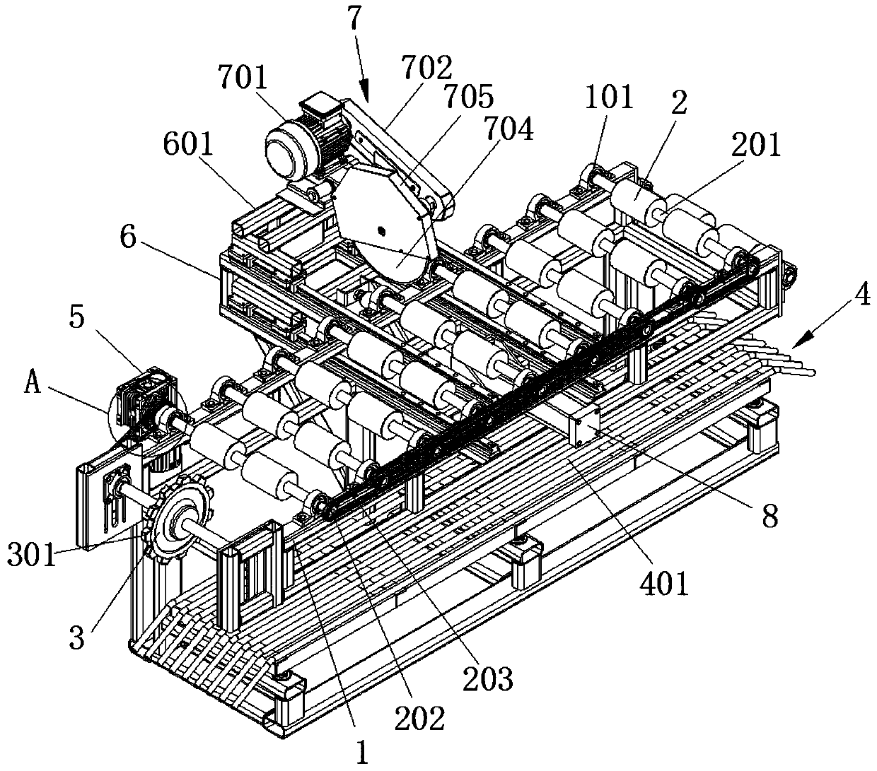
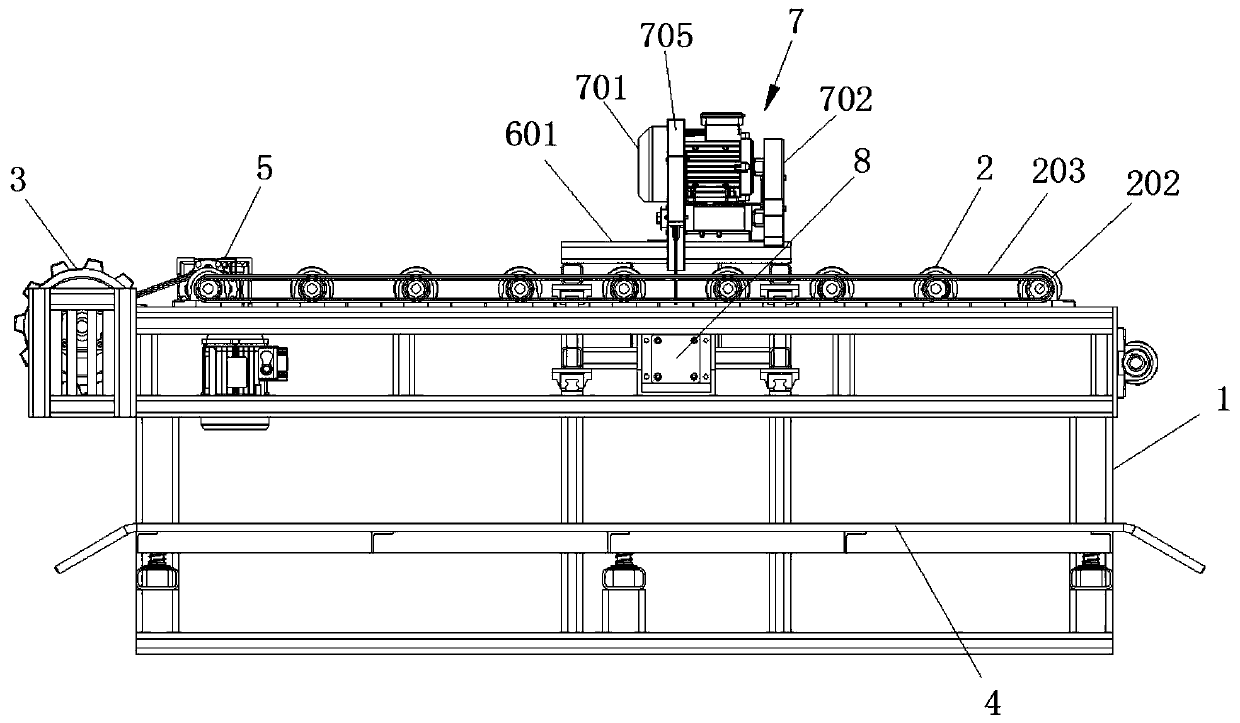
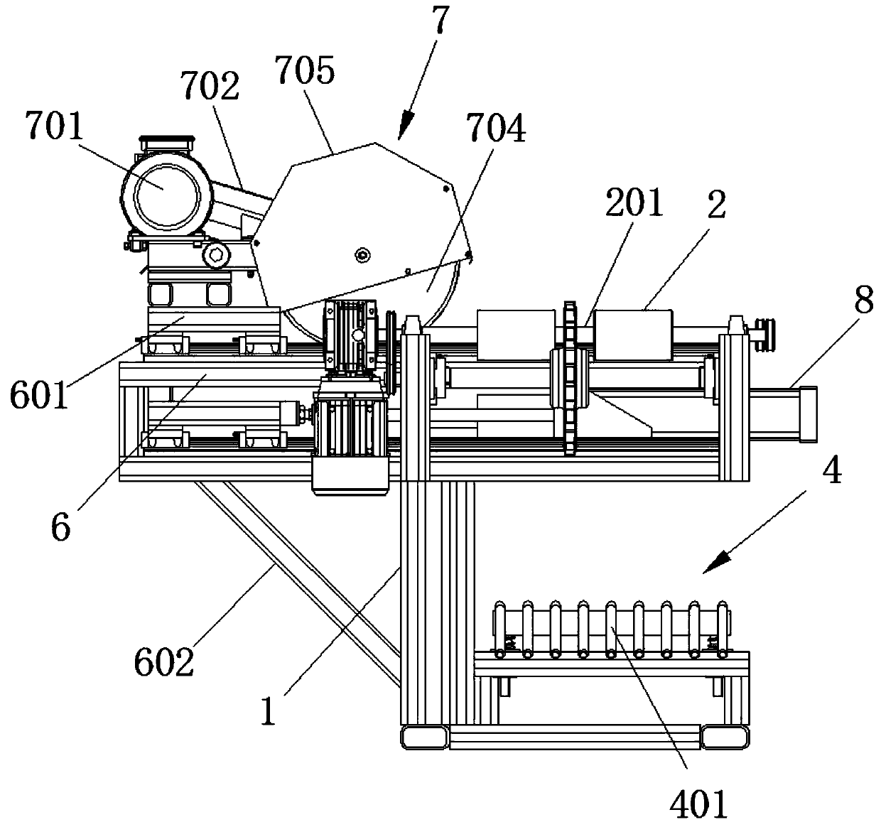
Waste rubber track splitting cutting tooling

A technology of waste rubber and rubber tracks, applied in recycling technology, plastic recycling, etc., can solve the problems of low work efficiency, displacement, and inability to adapt to cutting tools, so as to achieve smooth operation of equipment, ensure cutting effect, and improve cutting and recycling efficiency. Effect

Pending Publication Date: 2020-03-27
ZHENJIANG SHEN WARD MACHINERY CO LTD
View PDF0 Cites 1 Cited by
  • Summary
  • Abstract
  • Description
  • Claims
  • Application Information

AI Technical Summary

Problems solved by technology

The recycling of rubber track needs to be cut with a tool, but the track is generally in a ring structure and cannot adapt to the cutting of the tool, so it needs to be cut and unfolded into a long strip structure to adapt to the cutting line. At present, there is no corresponding The cutting device can cut the rubber track in sections, but it can only rely on manual cutting, the work efficiency is low, and it cannot meet the assembly line recycling operation; because the surface of the rubber track has a protruding structure, its ring structure is easy to contact with mechanical equipment when cutting Resistance will be generated between the rubber track, which will affect the normal conveying of the rubber track; usually when the cutting tool is cutting the rubber track, the force on the rubber track will cause its displacement, which will affect the cutting accuracy of the rubber track and the operation of the equipment. stability

Method used


Image

  • Waste rubber track splitting cutting tooling
  • Waste rubber track splitting cutting tooling
  • Waste rubber track splitting cutting tooling

Examples


Embodiment Construction

[0021] In order to make the technical solution of the present invention clearer, the present invention will be further described below in conjunction with the accompanying drawings. Any solution obtained by equivalent replacement and conventional reasoning of the technical features of the technical solution of the present invention falls within the protection scope of the present invention. The fixed connection mentioned in the present invention and the fixed arrangement are common connection methods in the mechanical field, and welding, bolt and nut connection and screw connection are all available.

[0022] In describing the present invention, it is to be understood that the terms "upper", "lower", "front", "rear", "left", "right", "vertical", "horizontal", "top" , "bottom", "inner", "outer" and other indicated orientations or positional relationships are based on the orientations or positional relationships shown in the drawings, and are only for the convenience of describin...


PUM


Abstract

A waste rubber track splitting cutting tooling comprises a rack, a roller, a driving wheel, a gear motor, a guide rail, a cutting device and a driving air cylinder. A plurality of groups of bearing seats are arranged on the rack, the roller is arranged between the bearing seats, a groove is arranged in the roller, first transmission wheels are arranged at a shaft end of the roller, and a first transmission chain is arranged between the first transmission wheels. The driving wheel is arranged at one end of the rack. The gear motor is arranged on one side of the rack, an output end of the gear motor is connected with the shaft end of the roller, a second transmission wheel is arranged at the output end of the gear motor, and a second transmission chain is arranged on the second transmissionwheel and is in transmission connection with the driving wheel. The guide rail is transversely arranged on the rack, a sliding support is arranged on the guide rail, and a cutting device is arranged on the sliding support. The driving air cylinder is arranged on the other side of the rack, an output end of the driving air cylinder is connected with the sliding support, the sliding support is pulled through the driving air cylinder so that the cutting device cuts a rubber track, tedious manual cutting is omitted, and cutting efficiency of the rubber track is effectively improved.

Description

technical field [0001] The invention belongs to the technical field of waste rubber recycling, and in particular relates to a waste rubber crawler separation and cutting tool. Background technique [0002] Rubber tracks are tracks made of rubber and skeleton materials, which are widely used in construction machinery, agricultural machinery and military equipment. When these mechanical equipment are scrapped, a large number of waste rubber tracks will be produced. These rubber tracks not only contain rubber, but also steel wires and iron embedded parts, and there are several groups of iron teeth arranged in the middle of the surface of the rubber track, which has a certain recycling capacity. value. The recycling of rubber track needs to be cut with a tool, but the track is generally in a ring structure and cannot adapt to the cutting of the tool, so it needs to be cut and unfolded into a long strip structure to adapt to the cutting line. At present, there is no correspondin...

Claims


Application Information

Patent Timeline
Patent Type & Authority Applications(China)
IPC IPC(8): B29B17/00B29B17/04
CPCB29B17/00B29B17/04B29B2017/044Y02W30/62
Inventor 俞世顺沈秀昌陈友朱雪梅
Owner ZHENJIANG SHEN WARD MACHINERY CO LTD
Why Eureka
Try Eureka