Automatic stamping machine facilitating inkpad adding
An automatic stamping machine and ink pad technology, applied in the field of stamping machines, can solve problems such as difficulty in grasping the position and direction of stamping, frequent contamination of ink pads, and affecting the efficiency of stamping, so as to ensure continuity and stability, and ensure stamping effect, the effect of ensuring continuity
- Summary
- Abstract
- Description
- Claims
- Application Information
AI Technical Summary
Problems solved by technology
Method used
Image
Examples
no. 1 example
[0020] Such as figure 1 As shown, an automatic stamping machine that is convenient for adding ink pads includes a base 1, a bracket 2 and a slider 3, a bracket 2 is installed on the right side of the top of the base 1, the bracket 2 is perpendicular to the base 1, and the bracket 2 is slidably provided with The slider 3, the slider 3 can slide vertically on the bracket 2, and also includes the outer casing 4, the mounting plate 5, the first spring 6, the stamp mechanism 7, the electric paper output roller 8 and the pressure wheel 9, the slider The left end face of 3 is connected with outer casing 4, and outer casing 4 is parallel to base 1, is provided with mounting plate 5 slidingly in outer casing 4, and mounting plate 5 can slide up and down in outer casing 4, and mounting plate 5 and outer casing 4 The first spring 6 is connected between them, the bottom of the mounting plate 5 is provided with a stamping mechanism 7 that can move thereon, the left and right sides of the b...
no. 2 example
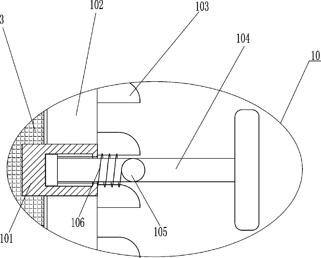
[0025] On the basis of the first embodiment, such as image 3 As shown, a fixed assembly 10 is also included, and the fixed assembly 10 includes a sliding frame 101, convex teeth 103, connecting rod 104, clamping rod 105 and a third spring 106, the right side of the slider 3 is fixedly connected with the sliding frame 101, and the bracket 2 There is a chute 102 for the passage of the sliding frame 101 on the right side. A connecting rod 104 is slidably connected in the sliding frame 101. The connecting rod 104 can move left and right in the sliding frame 101. Between the connecting rod 104 and the right end of the sliding frame 101 A third spring 106 is connected, and the third spring 106 is sleeved on the outside of the connecting rod 104 . The middle part of the connecting rod 104 is connected with a clamping rod 105 .
[0026]When the outer casing 4 moves downward freely and drives the slider 3 to move downward, it drives the slide frame 101 to move downward through the chu...
no. 3 example
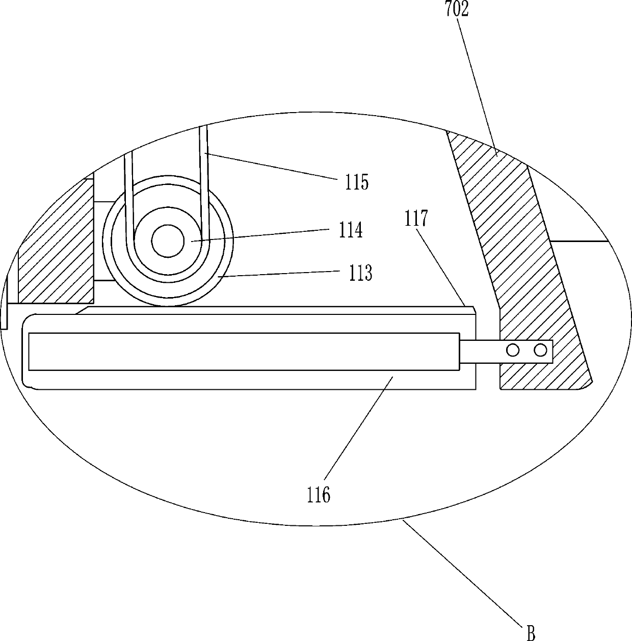
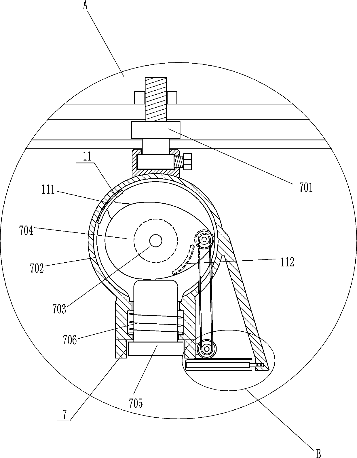
[0028] On the basis of the second embodiment, such as figure 2 and Figure 4 As shown, also include feeding device 11, feeding device 11 includes outer arc rack 111, inner arc rack 112, gear 113, sprocket wheel 114, chain 115, ink pad box 116 and transmission rack 117, The bottom of the right side of the inner shell 702 is slidingly connected with an ink pad box 116, which is set horizontally, and the top of the ink pad box 116 is connected with a transmission rack 117, which is connected to the ink pad box 116 by bolts, elliptical The cam 704 is connected with an outer arc rack 111 and an inner arc rack 112, the right side of the inner middle part of the inner housing 702 and the outer lower right side of the inner housing 702 are rotatably connected with a gear 113, and the outer arc rack 111 and the inner arc rack 112 can be meshed with the gear 113, the upper and lower two gears 113 are connected with a sprocket 114, and the upper and lower two sprockets 114 are connecte...
PUM
 Abstract
Description
Claims
Application Information
 - R&D
- Intellectual Property
- Life Sciences
- Materials
- Tech Scout
- Unparalleled Data Quality
- Higher Quality Content
- 60% Fewer Hallucinations
Browse by: Latest US Patents, China's latest patents, Technical Efficacy Thesaurus, Application Domain, Technology Topic, Popular Technical Reports.
© 2025 PatSnap. All rights reserved.Legal|Privacy policy|Modern Slavery Act Transparency Statement|Sitemap|About US| Contact US: help@patsnap.com


