An embossing mechanism combining a pneumatic component with a connecting rod assembly

A technology of connecting rod components and pneumatic components, which is applied in relief decorations, decorative arts, etc., can solve the problems of embossing mechanism occupying space, complicated programming, poor versatility, etc., to save space, ensure horizontal effects, and save costs Effect

Active Publication Date: 2021-06-15
深圳市合利士智能装备有限公司
View PDF0 Cites 0 Cited by
  • Summary
  • Abstract
  • Description
  • Claims
  • Application Information

AI Technical Summary

Problems solved by technology

[0005] Aiming at the deficiencies of the prior art, the present invention provides an embossing mechanism combining a pneumatic element with a connecting rod assembly, which has an optimized structural layout to achieve the advantages of space saving, cost saving, simple procedure and strong versatility, and solves the problem of embossing The mechanism takes up space, the structure is complex, the cost is high, the programming is complicated, and the versatility is poor

Method used


Image

  • An embossing mechanism combining a pneumatic component with a connecting rod assembly
  • An embossing mechanism combining a pneumatic component with a connecting rod assembly
  • An embossing mechanism combining a pneumatic component with a connecting rod assembly

Examples


Embodiment 1

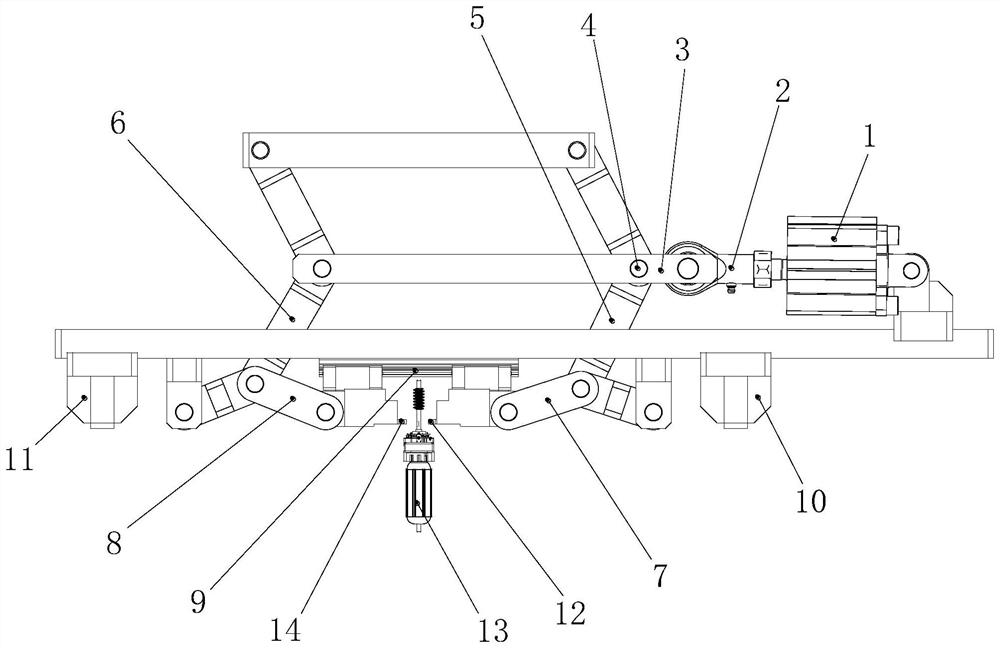
[0031] Embodiment one please refer to figure 1 , figure 2 , Figure 5 and Figure 8, an embossing mechanism in which a pneumatic element is combined with a connecting rod assembly, including a cylinder 1 and a table top, the cylinder 1 is fixedly mounted on the table top, the output end of the cylinder 1 is fixedly mounted with a connector 2, and on the connector 2 The driving rod 3 is fixedly connected, the connecting pin 4 is movably installed on the driving rod 3 and the connecting pin 4 can rotate freely on the driving rod 3, and the output connecting rod A5 is also movably connected on the connecting pin 4, and the output connecting rod A5 is also movably connected. The rod A5 is composed of two short rods, and the connecting pin 4 is arranged at the overlapping position of the two short rods. The two short rods of the output connecting rod A5 can rotate around the connecting pin 4 and the output connecting rod A5 passes through The connecting pin 4 is rotatably conne...

Embodiment 2

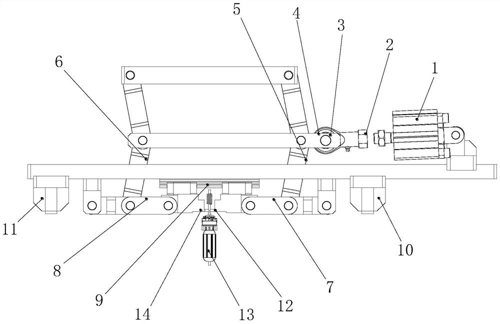
[0034] Embodiment 2 Please refer to image 3 , Figure 6 and Figure 8 , an embossing mechanism in which a pneumatic element is combined with a connecting rod assembly, including a cylinder 1 and a table top, the cylinder 1 is fixedly mounted on the table top, the output end of the cylinder 1 is fixedly mounted with a connector 2, and on the connector 2 The driving rod 3 is fixedly connected, the connecting pin 4 is movably installed on the driving rod 3 and the connecting pin 4 can rotate freely on the driving rod 3, and the output connecting rod A5 is also movably connected on the connecting pin 4, and the output connecting rod A5 is also movably connected. The rod A5 is composed of two short rods, and the connecting pin 4 is arranged at the overlapping position of the two short rods. The two short rods of the output connecting rod A5 can rotate around the connecting pin 4 and the output connecting rod A5 passes through The connecting pin 4 is rotatably connected with the ...

Embodiment 3

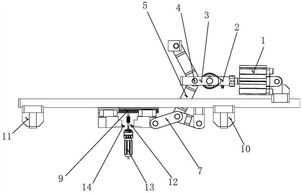
[0038] see Figure 4 , Figure 7 and Figure 8 , an embossing mechanism in which a pneumatic element is combined with a connecting rod assembly, including a cylinder 1 and a table top, the cylinder 1 is fixedly mounted on the table top, the output end of the cylinder 1 is fixedly mounted with a connector 2, and on the connector 2 The driving rod 3 is fixedly connected, the connecting pin 4 is movably installed on the driving rod 3 and the connecting pin 4 can rotate freely on the driving rod 3, and the output connecting rod A5 is also movably connected on the connecting pin 4, and the output connecting rod A5 is also movably connected. The rod A5 is composed of two short rods, and the connecting pin 4 is arranged at the overlapping position of the two short rods. The two short rods of the output connecting rod A5 can rotate around the connecting pin 4 and the output connecting rod A5 passes through The connecting pin 4 is rotatably connected with the driving rod 3, the lower...


PUM


Abstract

The invention relates to the technical field of embossing mechanisms, and discloses an embossing mechanism in which a pneumatic element is combined with a connecting rod assembly. The novel structure of the invention is optimized to save space, save cost, have simple procedures and strong versatility. It enables the mechanism to amplify simple small output actuators through the link mechanism to achieve high output, and the deeper the pressing, the greater the output, which perfectly matches the output of the embossing process. The embossing depth is adjustable, and it is suitable for various sizes of pieces to be embossed , improve the versatility, stability and work efficiency of the organization. Bilateral drive only needs one power element to achieve the effect of bilateral drive, and the embossing depth is also deeper. Using the linkage effect of several output rods can ensure that the two embossing knives are more stable when they move relative to each other, and at the same time adjust the embossing knife. Run depth is more convenient.

Description

technical field [0001] The invention relates to the technical field of embossing mechanisms, in particular to an embossing mechanism in which a pneumatic element is combined with a connecting rod assembly. Background technique [0002] The embossing mechanisms currently used are: Pneumatic press: use a large bore cylinder for embossing, the power source is air pressure; hydraulic press: use a hydraulic cylinder for embossing, the power source is hydraulic; electric press: use an electric cylinder For embossing, the power source is a motor; a small electric punch. [0003] At present, the embossing mechanism on the market takes up space, has a complicated structure, high cost, complicated programming and poor versatility. At present, when the automation equipment on the market requires multiple pressures, it is necessary to replace the actuators with different outputs to achieve the corresponding embossing function, resulting in a wide variety of mechanisms, increasing the a...

Claims


Application Information

Patent Timeline
Patent Type & Authority Patents(China)
IPC IPC(8): B44B5/00B44B5/02
CPCB44B5/0052B44B5/02B44B5/026
Inventor 周华国廖建勇万华保
Owner 深圳市合利士智能装备有限公司
Why Eureka
Try Eureka