
Small product batch feeding device and implementation method thereof

A product and equipment technology, applied in the field of small product batch feeding equipment, can solve the problem of low feeding efficiency

Active Publication Date: 2020-03-27
东阳东磁自动化科技有限公司
View PDF5 Cites 14 Cited by
  • Summary
  • Abstract
  • Description
  • Claims
  • Application Information

AI Technical Summary

Problems solved by technology

[0002] The soft magnetic department of Dong Magnetic Group currently needs to load a material product to the grinding machine. The existing feeding method is mostly manual feeding. At present, most of the feeding mechanisms on the market are single product feeding, and the feeding efficiency is low.

Method used


Image

  • Small product batch feeding device and implementation method thereof
  • Small product batch feeding device and implementation method thereof
  • Small product batch feeding device and implementation method thereof

Examples


Embodiment 1

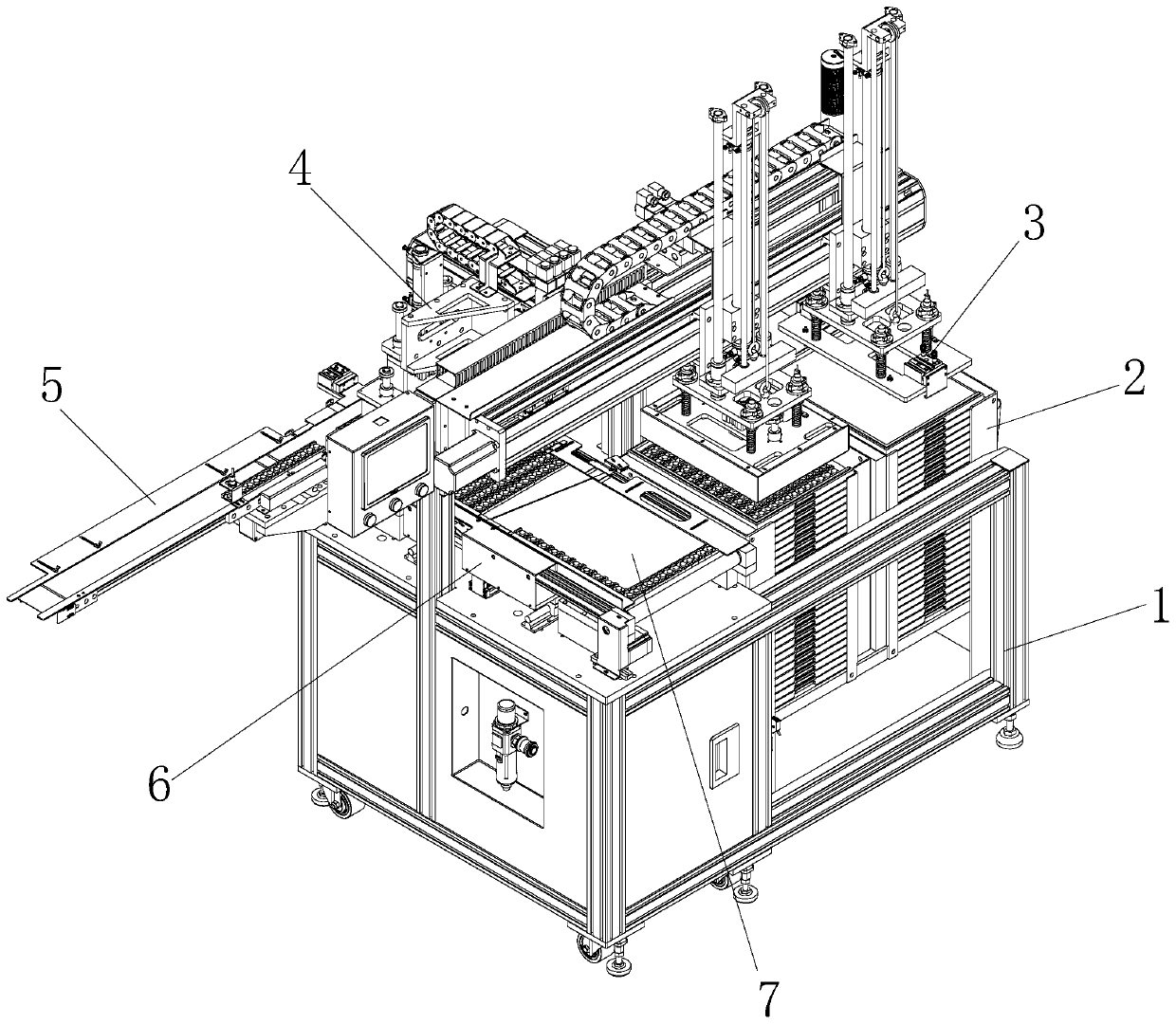
[0043] see Figure 1-15 , the present invention provides the following technical solutions: a batch feeding device for small products, including a workbench 1, a tray storage mechanism 2 is placed inside the workbench 1, and the two sides of the tray storage mechanism 2 above the workbench 1 are respectively connected with Magnetic suction feeding mechanism 3 and transition device 7, one side of transition device 7 is provided with adjustment mechanism 6, one end of transition device 7 is provided with magnetic suction transplanting mechanism 4, and one side of magnetic suction transplanting mechanism 4 is provided with discharging Agency 5.

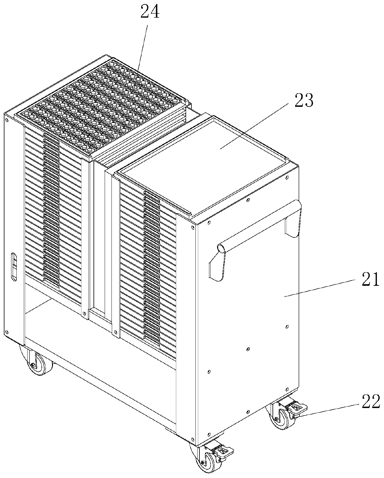
[0044]Further, the tray storage mechanism 2 includes a storage rack 21, the four corners of the bottom of the storage rack 21 are respectively connected with casters 22, the inside of the storage rack 21 is respectively provided with an empty tray station 23 and a full tray station 24, and the empty tray Station 23 is located on one sid...

Embodiment 2

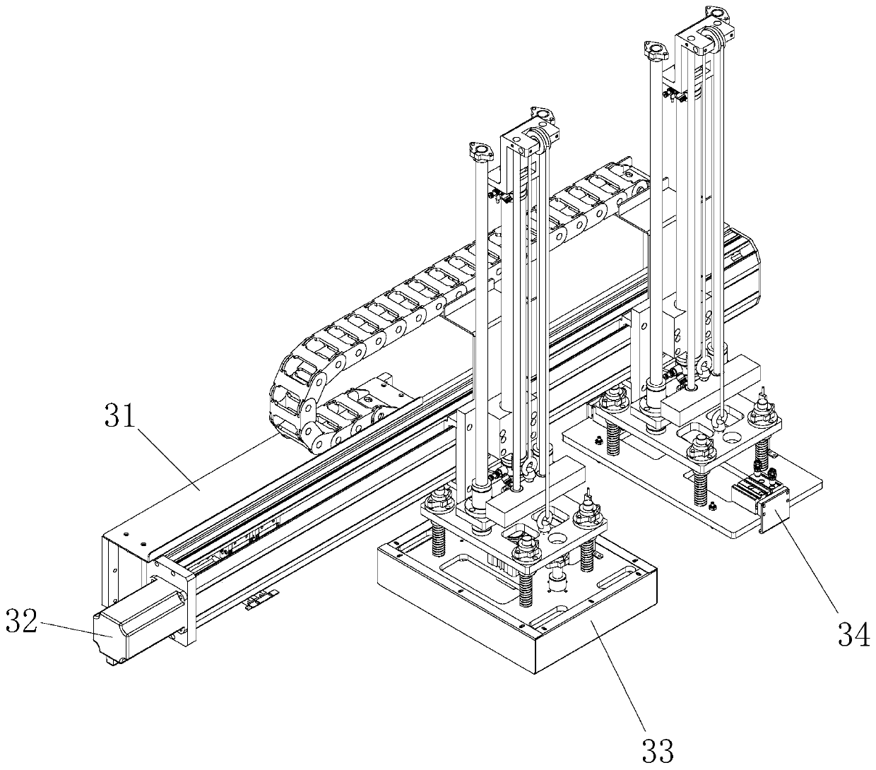
[0067] The difference between this embodiment and Embodiment 1 is that further, the loading and unloading mechanism 33 includes a lifting mechanism 8, a buffer mechanism 9 and a magnetic suction mechanism 35, wherein the lifting mechanism 8 is installed on the linear module 31 of the magnetic suction feeding mechanism. On the slider, the bottom of the lifting mechanism 8 is connected with a buffer mechanism 9, and the bottom of the buffer mechanism 9 is connected with a magnetic suction mechanism 35. The empty tray mechanism 34 includes a lifting mechanism 8, a buffer mechanism 9 and a splint mechanism 36. The lifting mechanism 8 is installed on the On the slider of the linear module 31 of the magnetic suction feeding mechanism, a buffer mechanism 9 is connected below the lifting mechanism 8 , and a splint mechanism 36 is connected below the buffer mechanism 9 .

[0068]Further, the magnetic suction mechanism 35 includes a guard plate 351, a magnetic suction cylinder 352, a mag...


PUM


Abstract

The invention discloses a small product batch feeding device. The small product batch feeding device comprises a workbench, wherein a tray storage mechanism is arranged in the workbench; a magnetic attraction feeding mechanism and a transition device are connected to the positions, corresponding to the two sides of the tray storage mechanism, above the workbench; an adjusting mechanism is arrangedon one side of the transition device; a magnetic attraction transplanting mechanism is arranged at one end of the transition device; and a discharging mechanism is arranged on one side of the magnetic attraction transplanting mechanism. The invention further discloses an implementation method of the small product batch feeding device. According to the small product batch feeding device and the implementation method thereof, a linear module of the magnetic attraction feeding mechanism is used for moving a feeding and discharging mechanism and an empty tray clamping mechanism, products in traysare moved to the transition device through the feeding and discharging mechanism, empty trays in a full tray station are clamped into an empty tray station through the empty tray clamping mechanism,and therefore the labor intensity of workers is greatly reduced.

Description

technical field [0001] The invention belongs to the technical field of product feeding, and in particular relates to a batch feeding device for small products and a realization method thereof. Background technique [0002] The soft magnetic department of Dong Magnetic Group currently needs to load a material product to the grinding machine. The existing feeding method is mostly manual feeding. Currently, most of the feeding mechanisms on the market are single product feeding, and the feeding efficiency is low. Contents of the invention [0003] The object of the present invention is to provide a batch feeding device for small products, so as to solve the problems raised in the above-mentioned background technology. The batch feeding equipment for small products provided by the present invention has the characteristics that the products can be fed in batches quickly, and the production efficiency is greatly improved. [0004] Another object of the present invention is to p...

Claims


Application Information

Patent Timeline
IPC IPC(8): B65G47/92B65G59/02B65G61/00B65G47/22B65G43/08B65G47/04
CPCB65G43/08B65G47/04B65G47/22B65G47/92B65G59/02B65G61/00
Inventor 黄旺刘晋胡意周
Owner 东阳东磁自动化科技有限公司
Learn More