A system for pre-embedding electrical pipelines in a secondary structure and its implementation method

A secondary structure and pipeline technology, applied in the installation of electrical components, building components, cables, etc., can solve problems such as complicated construction steps, and achieve the effect of ensuring the fixing effect and facilitating installation and replacement work

A secondary structure and pipeline technology, applied in the installation of electrical components, building components, cables, etc., can solve problems such as complicated construction steps, and achieve the effect of ensuring the fixing effect and facilitating installation and replacement work

CN110924564BActive Publication Date: 2021-02-23CHINA MCC17 GRP

Image

  • A system for pre-embedding electrical pipelines in a secondary structure and its implementation method
  • A system for pre-embedding electrical pipelines in a secondary structure and its implementation method
  • A system for pre-embedding electrical pipelines in a secondary structure and its implementation method

Examples


Embodiment 1

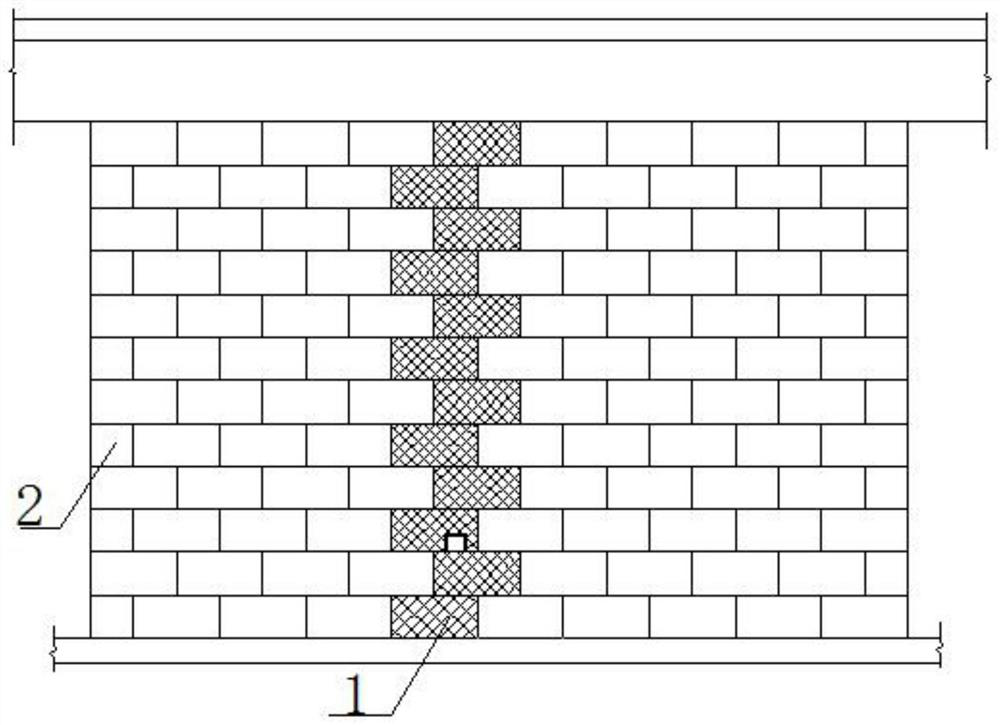
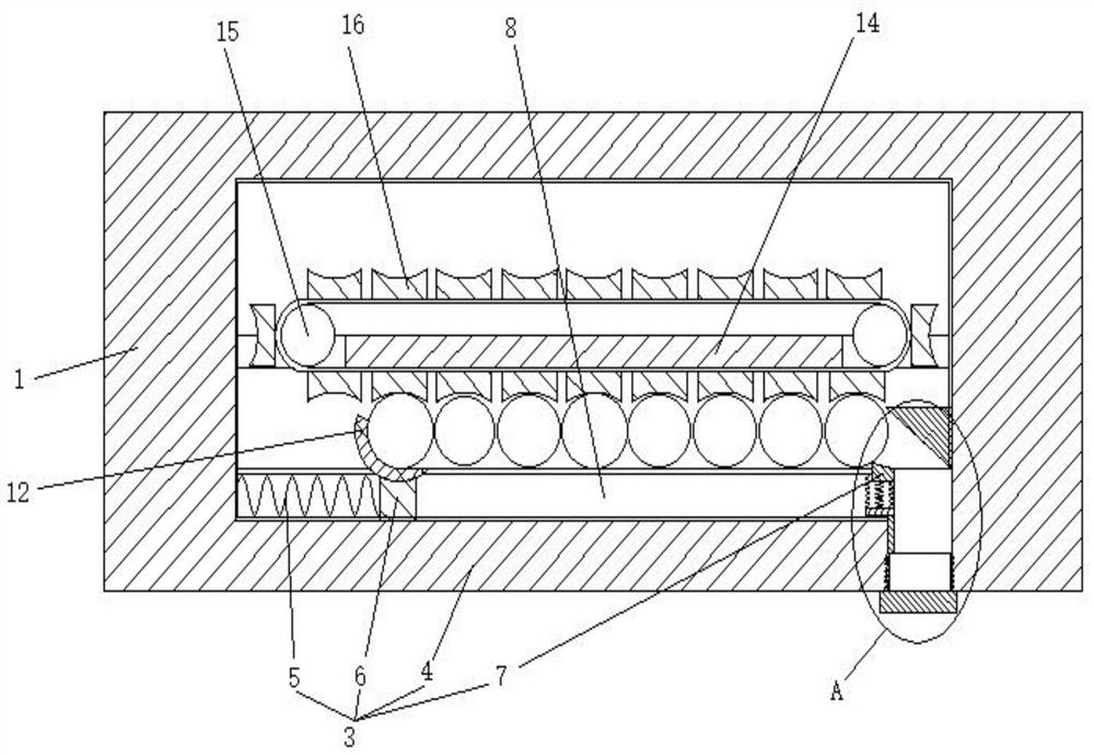
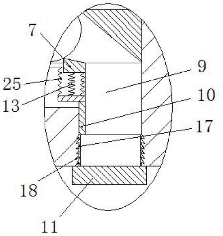
[0029] Such as Figure 1 to Figure 4 As shown, a pre-embedded electrical pipeline system in a secondary structure includes a prefabricated brick wall and a masonry wall 2. The prefabricated brick wall is stacked at the preset pipeline position by several prefabricated bricks 1 arranged in an orderly manner. In the masonry wall 2, a junction box is added to the bottom prefabricated brick 1 at the position of the preset pipeline, and a fixed line card connected to the junction box is embedded in each prefabricated brick 1 located directly above the junction box 3. The electric pipeline is directly fixed by connecting the fixed line card 3 with the junction box. The fixed line card 3 includes a housing 4, a first spring 5, a clip 6 and a wedge-shaped block 7, the housing 4 is a hollow structure with upper and lower notches, and the inner wall of the housing 4 is provided with a positioning structure and a guide groove 8 , where the positioning structure can limit the position of...

Embodiment 2

[0038] Such as Figure 1 to Figure 4 As shown, a method for implementing an electrical pipeline pre-embedded system in a secondary structure includes the following steps,

[0039] Step 1. First, stack the masonry wall 2 and reserve a suitable space at the preset pipeline position. Several orderly arranged prefabricated bricks 1 are stacked on the masonry wall 2 at the preset pipeline position. Inside, the cavity 22 of the first waterproof layer 21 on the stacking groove 19 is opposite to the cavity 22 of the first waterproof layer 21 on the stacking protrusion 20, and the first waterproof layer 21 on the stacking groove 19 The first waterproof layer 21 on the stacking protrusion 20 is in a compressed state after stacking, and it is ensured that all shells 4 are coaxial and all positioning structures are located on the same side;

[0040] Step 2. Finally, the electrical pipelines are laid in the prefabricated brick 1, and the cover plate 11 matching the housing 4 is put on the...


PUM


Abstract

The invention discloses a system for pre-embedding electrical pipelines in a secondary structure and an implementation method, belonging to the field of pre-embedding electrical pipelines in buildings. Each prefabricated brick is embedded with a fixed line card. The fixed line card includes a shell, a first spring, a clip and a wedge-shaped stopper. The inner wall of the shell is provided with a positioning structure, a guide groove, a notch, and a groove. A fixed block is inserted at the mouth, and a cover plate is matched and connected to the housing at the notch. The first spring is set in the guide groove. One end of the clip is fixedly connected with the first spring, and the other end of the clip is provided with a shovel. A mounting plate is movably connected in the groove, and the side of the mounting plate facing away from the positioning structure is in conflict with the fixed block. The mounting plate is provided with a second spring and a third spring. One end of the second spring is connected to the wedge-shaped stopper, and one end of the third spring is connected to the In the guide groove, the width of the wedge-shaped stopper is equal to the width of the guide groove, which effectively solves the existing problems of complicated construction and unfavorable replacement, realizes high working efficiency and saves later maintenance costs.

Description

technical field [0001] The invention belongs to the technical field of pre-embedded electric pipelines in buildings, and in particular relates to a pre-embedded system for electrical pipelines in a secondary structure and an implementation method. Background technique [0002] In the current civil construction industry, the pre-embedded construction of electrical pipelines in the secondary structure generally adopts the method of building brick walls first, then using chisels and electric hammers to chisel out pipe grooves, and finally repairing them with mortar. Although the construction technology content is low, the construction The progress is slow and the quality is poor, and for cement bricks, red bricks and thin masonry walls, it is easy to break bricks, damage the wall structure, and irregular pipe grooves. There are also a small number of prefabricated hollow bricks set on the outside of the electrical pipeline for construction. This method is complicated to operate...

Claims


Application Information

Patent Timeline
23 Feb 2021
Publication
CN110924564B
IPC
E04B2/02; E04B1/66; E04C1/00; H02G1/00; H02G3/38
CPC
E04B1/665; E04B2/02; E04C1/00; H02G1/00; H02G3/38
Inventors
黄无忌; 于永睿