Lens treatment process for zoom LED lamp
A technology of LED lamps and processing technology, which is applied in the direction of headlights, semiconductor devices of light-emitting elements, lighting and heating equipment, etc., can solve the problems that drivers cannot confirm road conditions well, increase the danger of driving at night, and affect lighting effects, etc. To achieve the effect of reducing the blind area of the light, reducing the generation of light spots, and avoiding imaging problems
- Summary
- Abstract
- Description
- Claims
- Application Information
AI Technical Summary
Problems solved by technology
Method used
Image
Examples
Embodiment 1
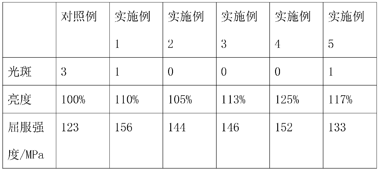
[0029] This embodiment provides a lens processing technology for a zoom LED lamp, which specifically includes the following steps:
[0030] S1: Use quartz sand to sandblast the outer curved surface or plane of the lens. After the treatment is completed, frost the protruding part of the lens corner to make the surface roughness of the outer curved surface or plane reach 30 μm, so that the lens corners protrude Partial surface roughness reaches 100μm;
[0031] S2: Put the lens into the polishing solution for polishing, and remove the scratches caused by sandblasting or grinding on the surface of the lens;
[0032] S3: Put the polished lens into the mixture of nitric acid, hydrofluoric acid and aqueous solution to clean, and remove the oil layer on the outer curved surface or plane surface of the lens;
[0033] S4: Rinse the pickled lens with cold water, then with hot water and distilled water, and finally put the lens into an oven for drying;
[0034] S5: Apply a layer of brig...
Embodiment 2
[0047] This embodiment provides a lens processing technology for a zoom LED lamp, which specifically includes the following steps:
[0048] S1: Use quartz sand to sandblast the outer curved surface or plane of the lens. After the treatment is completed, frost the protruding part of the lens corner to make the surface roughness of the outer curved surface or plane reach 35 μm, so that the lens corners protrude Partial surface roughness reaches 110μm;
[0049] S2: Put the lens into the polishing solution for polishing, and remove the scratches caused by sandblasting or grinding on the surface of the lens;
[0050] S3: Put the polished lens into the mixture of nitric acid, hydrofluoric acid and aqueous solution to clean, and remove the oil layer on the outer curved surface or plane surface of the lens;
[0051] S4: Rinse the pickled lens with cold water, then with hot water and distilled water, and finally put the lens into an oven for drying;
[0052] S5: Apply a layer of brig...
Embodiment 3
[0065] This embodiment provides a lens processing technology for a zoom LED lamp, which specifically includes the following steps:
[0066] S1: Use quartz sand to sandblast the outer curved surface or plane of the lens. After the treatment is completed, frost the protruding part of the lens corner to make the surface roughness of the outer curved surface or plane reach 38 μm, so that the lens corners protrude Partial surface roughness reaches 130μm;
[0067] S2: Put the lens into the polishing solution for polishing, and remove the scratches caused by sandblasting or grinding on the surface of the lens;
[0068] S3: Put the polished lens into a mixture of nitric acid, hydrofluoric acid and aqueous solution for cleaning, and remove the oil layer on the outer curved surface or plane surface of the lens;
[0069] S4: Rinse the pickled lens with cold water, then with hot water and distilled water, and finally put the lens into an oven for drying;
[0070] S5: Apply a layer of br...
PUM
| Property | Measurement | Unit |
|---|---|---|
| surface roughness | aaaaa | aaaaa |
| surface roughness | aaaaa | aaaaa |
| thickness | aaaaa | aaaaa |
Abstract
Description
Claims
Application Information
 - R&D
- Intellectual Property
- Life Sciences
- Materials
- Tech Scout
- Unparalleled Data Quality
- Higher Quality Content
- 60% Fewer Hallucinations
Browse by: Latest US Patents, China's latest patents, Technical Efficacy Thesaurus, Application Domain, Technology Topic, Popular Technical Reports.
© 2025 PatSnap. All rights reserved.Legal|Privacy policy|Modern Slavery Act Transparency Statement|Sitemap|About US| Contact US: help@patsnap.com

