
Head-mounted display optical module and equipment

A technology of optical modules and optical mirrors, applied in optics, optical components, magnifying glasses, etc., can solve the problems of light color shift, low optical efficiency, low light energy, etc.

Active Publication Date: 2020-03-27
SEEYA OPTRONICS LTD
View PDF8 Cites 3 Cited by
  • Summary
  • Abstract
  • Description
  • Claims
  • Application Information

AI Technical Summary

Problems solved by technology

[0003] In the existing design, the light emitted by the display panel in the virtual reality technology and the augmented reality technology has the problem of color shift at a large exit angle, that is, the large viewing angle, which will affect the image quality observed by the user
In addition, the energy of the light emitted by the display panel at a large exit angle is low, and the optical efficiency is also low.

Method used


Image

  • Head-mounted display optical module and equipment
  • Head-mounted display optical module and equipment
  • Head-mounted display optical module and equipment

Examples


Embodiment Construction

[0049] The present invention will be further described in detail below in conjunction with the accompanying drawings and embodiments. It should be understood that the specific embodiments described here are only used to explain the present invention, but not to limit the present invention. In addition, it should be noted that, for the convenience of description, only some structures related to the present invention are shown in the drawings but not all structures.

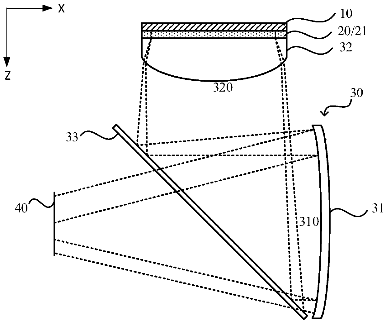
[0050] The head-mounted display optical module is used to image the picture displayed on the display panel on the user observation side, and the user can observe the image displayed on the display panel on the user observation side. The light emitted from the display panel is finally projected to the side observed by the user as parallel light. Since the larger the incident angle of the light projected to the user's observation side, the larger the viewing angle of the user's observation image, the larger the size...


PUM


Abstract

The invention provides a head-mounted display optical module and equipment. The head-mounted display optical module is used for imaging a display image of a display panel at a user observation side, and comprises: an optical lens group which is located at a light-emitting display side of the display panel; and a protective layer on an optical path between the display panel and the optical lens group, wherein the protective layer comprises at least one first protective layer, the refractive index of the first protective layer continuously changes at least along the radial direction inside the first protective layer, the radial direction is located in the plane where the first protective layer is located, and the center of the first protective layer points to the edge of the first protectivelayer. The invention provides the head-mounted display optical module and the equipment, so that a user can observe a color cast-free image under a large field angle, and the optical efficiency is improved.

Description

technical field [0001] The present invention relates to the field of head-mounted displays, in particular to a head-mounted display optical module and equipment. Background technique [0002] Both virtual reality technology and augmented reality technology are computer simulation systems that can create and experience virtual worlds, and have been widely used in game entertainment, education, medical care, military simulation and other aspects. [0003] In the existing design, the light emitted by the display panel in the virtual reality technology and the augmented reality technology has the problem of color shift at a large exit angle, that is, a large viewing angle, which will affect the image quality observed by the user. In addition, the energy of light emitted by the display panel at a large outgoing angle is low, and the optical efficiency is also low. Contents of the invention [0004] The present invention provides a head-mounted display optical module and equipm...

Claims


Application Information

Patent Timeline
IPC IPC(8): G02B27/01
CPCG02B27/0172G02B2027/015G02B25/001G02B17/08G02B3/0087G02B2027/0116G02B5/10G02B1/14
Inventor 邱孙杰牛磊
Owner SEEYA OPTRONICS LTD
Learn More