Multi-energy system combined installation planning method based on global benefit maximization

A multi-energy, optimization method technology, applied in the field of electric power, can solve the problem of not finding the peak shaving problem, the influence of the safe and stable operation of the power grid, and the difficulty of adapting

Pending Publication Date: 2020-03-27
STATE GRID LIAONING ECONOMIC TECHN INST +2
View PDF4 Cites 5 Cited by
  • Summary
  • Abstract
  • Description
  • Claims
  • Application Information

AI Technical Summary

Problems solved by technology

This method can be dealt with when the scale of wind power access in the power grid is small. With the large-scale development of wind power, especially the commissioning of 10-million-kilowatt wind power bases, relying on the peak-shaving surplus of thermal power units during low-valley peak-shaving to overcome wind power The way of fluctuation will be difficult to adapt, and it will also have a great impact on the safe and stable operation of the power grid
[0003] Affected by the power supply structure and heating demand in northern my country, the problem of low-load peak-shaving is prominent. At present, pumped storage and limited new energy output are mainly used to alleviate the power grid peak-shaving problem. No effective means have been found to completely solve the peak-shaving problem.

Method used

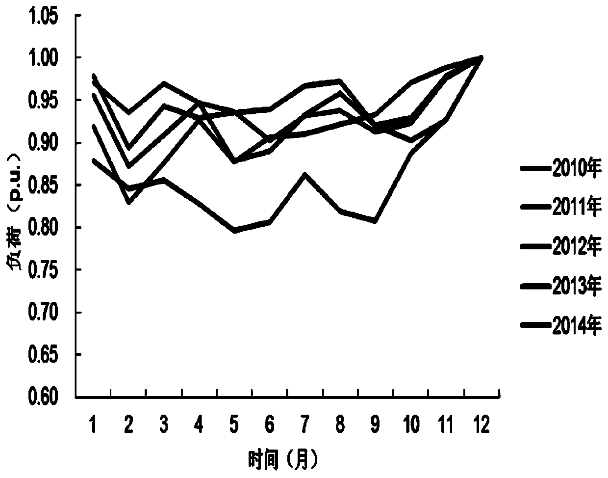
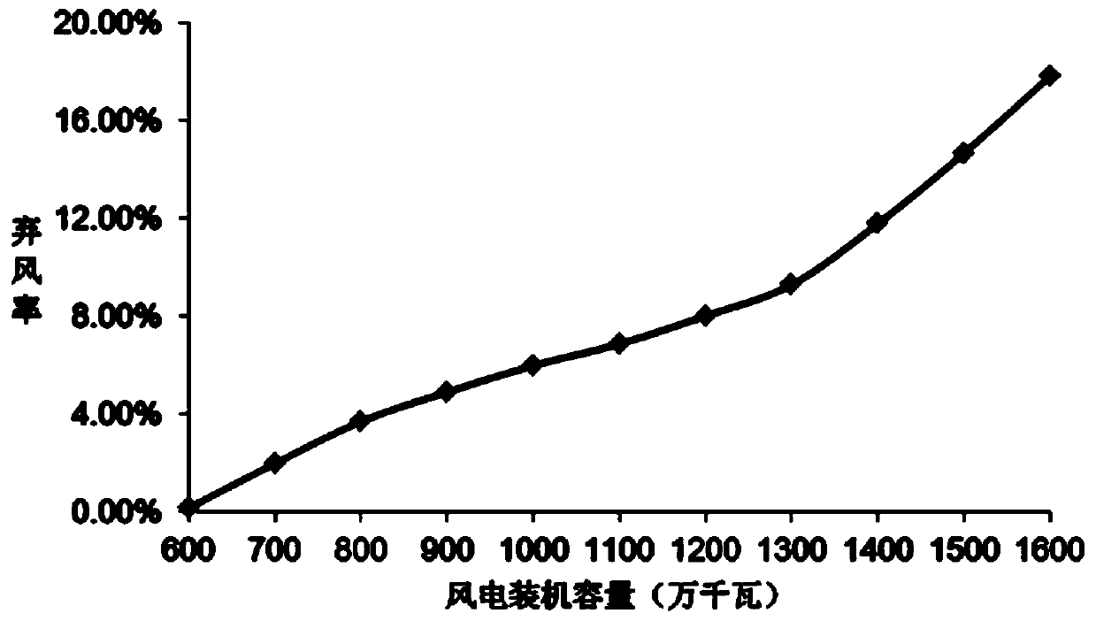
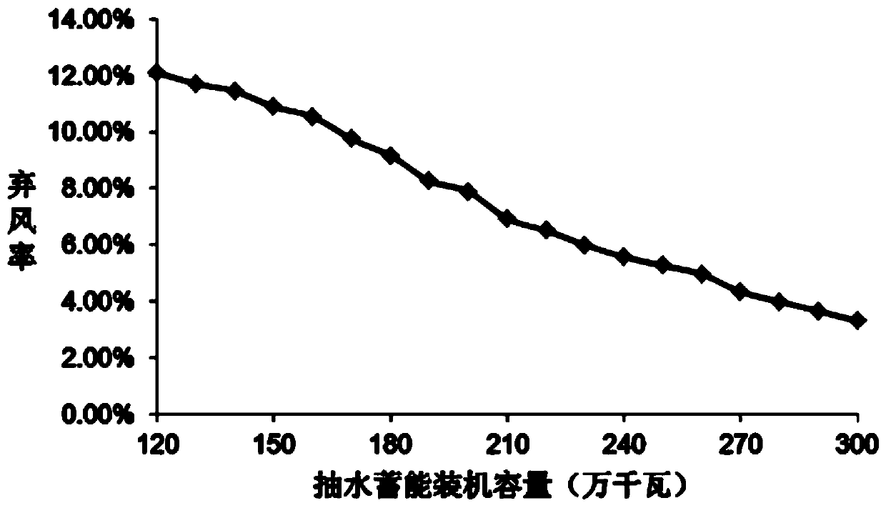

Image

  • Multi-energy system combined installation planning method based on global benefit maximization
  • Multi-energy system combined installation planning method based on global benefit maximization
  • Multi-energy system combined installation planning method based on global benefit maximization

Examples


Embodiment Construction

[0065] The following will clearly and completely describe the technical solutions in the examples of the present invention with reference to the drawings in the embodiments of the present invention. Apparently, the described embodiments are only some of the embodiments of the present invention, but not all of them. Based on the embodiments of the present invention, other embodiments obtained by persons of ordinary skill in the art without making creative efforts all belong to the protection scope of the present invention.

[0066] Such as Figure 9 as shown, Figure 9 It is a flowchart of multi-energy system combined installed capacity planning based on global benefit maximization in the present invention. A multi-energy system joint installed capacity planning method based on global benefit maximization according to the present invention comprises the following steps:

[0067] Step 1: Construct the joint planning model of the pumped storage power station. The joint planni...


PUM


Abstract

The invention relates to the technical field of electric power, in particular to a multi-energy system combined installation planning method based on global benefit maximization. The method comprisesthe steps of constructing a pumped storage power station joint planning model; solving the planning model by using a two-layer optimization method; and obtaining a system planning result by using a Cplex optimization software. According to the method, the wind power absorption capacity of the northern areas can be improved, the disturbance rejection capacity and the wind power absorption capacityof the system are improved on the premise of considering the company benefits and social benefits, and the peak regulation capacity of the system after wind power grid connection is improved. The method also consider the factors, such as the fluctuation of the system load and the wind power, a power supply structure, the power grid peak shaving capacity, the influence of the wind power on the peakshaving capacity after the power wind accesses in a power grid, etc., comprehensively, and can quantitatively evaluate the limitation degree of the power grid peak shaving on the wind power acceptance capacity. The method is helpful for meeting the energy-saving and environment-friendly, clean energy admission and other political demands in China, and can be used for improving the power grid power supply structure in China, reducing the power generation cost and improving the safe and stable operation capability of the power grid.

Description

technical field [0001] The invention relates to the field of electric power technology, in particular to a multi-energy system joint installed capacity planning method based on global benefit maximization. Background technique [0002] Wind power is highly random, intermittent and uncontrollable. The output characteristics of wind power have the characteristics of anti-peak regulation, that is, when the load is low, the output of conventional thermal power units decreases, but at this time the output of wind power units increases significantly. In order to ensure that the system frequency is within the normal range, it is necessary to further reduce the output of thermal power units. In the absence of accurate wind power forecasting, a peak regulation surplus close to the maximum output of wind power should be left in the power grid to balance the increase in wind power output when the load is low. part. This method can be dealt with when the scale of wind power access in ...

Claims


Application Information

Patent Timeline
Patent Type & Authority Applications(China)
IPC IPC(8): H02J3/00H02J3/38H02J3/28
CPCH02J3/00H02J3/28H02J3/008Y02E70/30Y02E10/76
Inventor 张娜张明理潘霄梁毅高靖刘兴龙王义贺朱赫炎宋坤赵琳仲崇飞侯依昕刘禹彤满林坤李纯正王鹤霏
Owner STATE GRID LIAONING ECONOMIC TECHN INST
Why Eureka
Try Eureka