
Pipeline analog-to-digital converter

An analog-to-digital converter technology, applied in the field of pipelined analog-to-digital converters, can solve the problems of large circuit area, limited design freedom, unity gain buffer occupation, etc., and achieve the effect of good accuracy and stable operation

Pending Publication Date: 2020-03-27
REALTEK SEMICON CORP
View PDF6 Cites 0 Cited by
  • Summary
  • Abstract
  • Description
  • Claims
  • Application Information

AI Technical Summary

Problems solved by technology

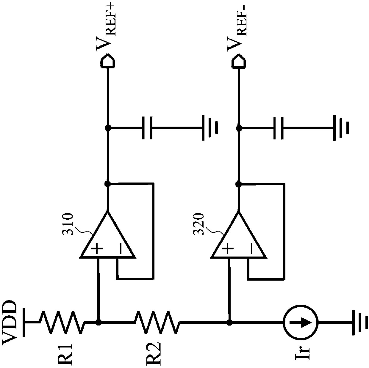
However the above conditions limit the reference voltage V REF+ and reference voltage V REF- degrees of design freedom
Furthermore, image 3 The unit gain buffers (unit gain buffer) 310 and 320 in the

Method used


Image

  • Pipeline analog-to-digital converter
  • Pipeline analog-to-digital converter
  • Pipeline analog-to-digital converter

Examples


Embodiment Construction

[0030] The technical terms used in the following description refer to the idioms in the technical field. If part of the terms is described or defined in this specification, the explanation of the part of terms is based on the description or definition of this specification.

[0031] The present disclosure includes pipelined analog-to-digital converters. Since some of the components included in the pipelined analog-to-digital converter of the present invention may be known components individually, the following describes the details of the known components without affecting the full disclosure and practicability of the device invention Will be omitted.

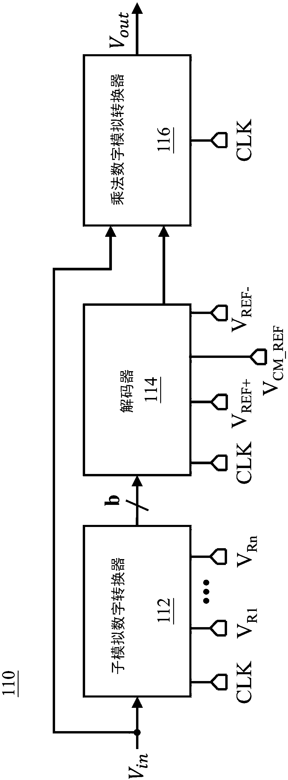
[0032] After careful research, the inventor found that by adjusting the reference voltage of the comparator of the multiplying digital-to-analog converter 116, or modifying the circuit design of the multiplying digital-to-analog converter 116, the ground or ground level can be used as the reference voltage V of the decoder 114. REF...


PUM


Abstract

The invention discloses a pipelined analog-to-digital converter. The pipelined analog-to-digital converter comprises a sub analog-to-digital converter, a multiplication digital-to-analog converter anda decoder, and the decoder provides a ground signal for the multiplication digital-to-analog converter. The sub-analog-to-digital converter is electrically connected with a ground pad through a firstmetal wire, and the decoder is electrically connected with the ground pad through a second metal wire.

Description

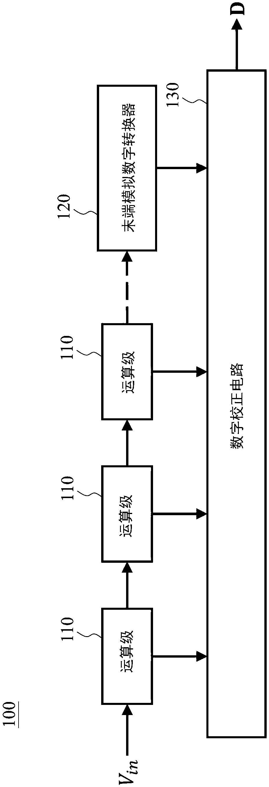
Technical field [0001] The present invention relates to a pipelined analog-to-digital converter (pipelined ADC, also known as pipeline ADC). Background technique [0002] figure 1 It is an existing pipelined analog-to-digital converter 100, which includes a plurality of serially connected arithmetic stages 110, a terminal analog-digital converter 120, and a digital correction circuit 130. Differential input signal V in After multiple stages of comparison, subtraction, and amplification, the output of each stage 110 and the output of the terminal analog-to-digital converter 120 are corrected by the correction circuit 130 to generate a digital code D, which is the differential input Signal V in The result after analog-digital conversion. The operation principle of the pipelined analog-to-digital converter 100 is well-known to those skilled in the art, so it will not be repeated here. [0003] figure 2 for figure 1 A functional block diagram of one of the operational stages 110 o...

Claims


Application Information

Patent Timeline
Patent Type & Authority Applications(China)
IPC IPC(8): H03M1/10
CPCH03M1/1033
Inventor 吴健铭雷良焕黄诗雄
Owner REALTEK SEMICON CORP
Learn More