
Electronic equipment module

A technology of electronic equipment and modules, which is applied in the electronic field and can solve problems such as poor wiring of electronic equipment

Inactive Publication Date: 2020-03-27
INSPUR BUSINESS MACHINE CO LTD
View PDF17 Cites 0 Cited by
  • Summary
  • Abstract
  • Description
  • Claims
  • Application Information

AI Technical Summary

Problems solved by technology

[0004] In view of this, the object of the present invention is to provide an electronic equipment module, which can effectively solve the problem of poor routing of electronic equipment wires

Method used


Image

  • Electronic equipment module
  • Electronic equipment module
  • Electronic equipment module

Examples


Embodiment Construction

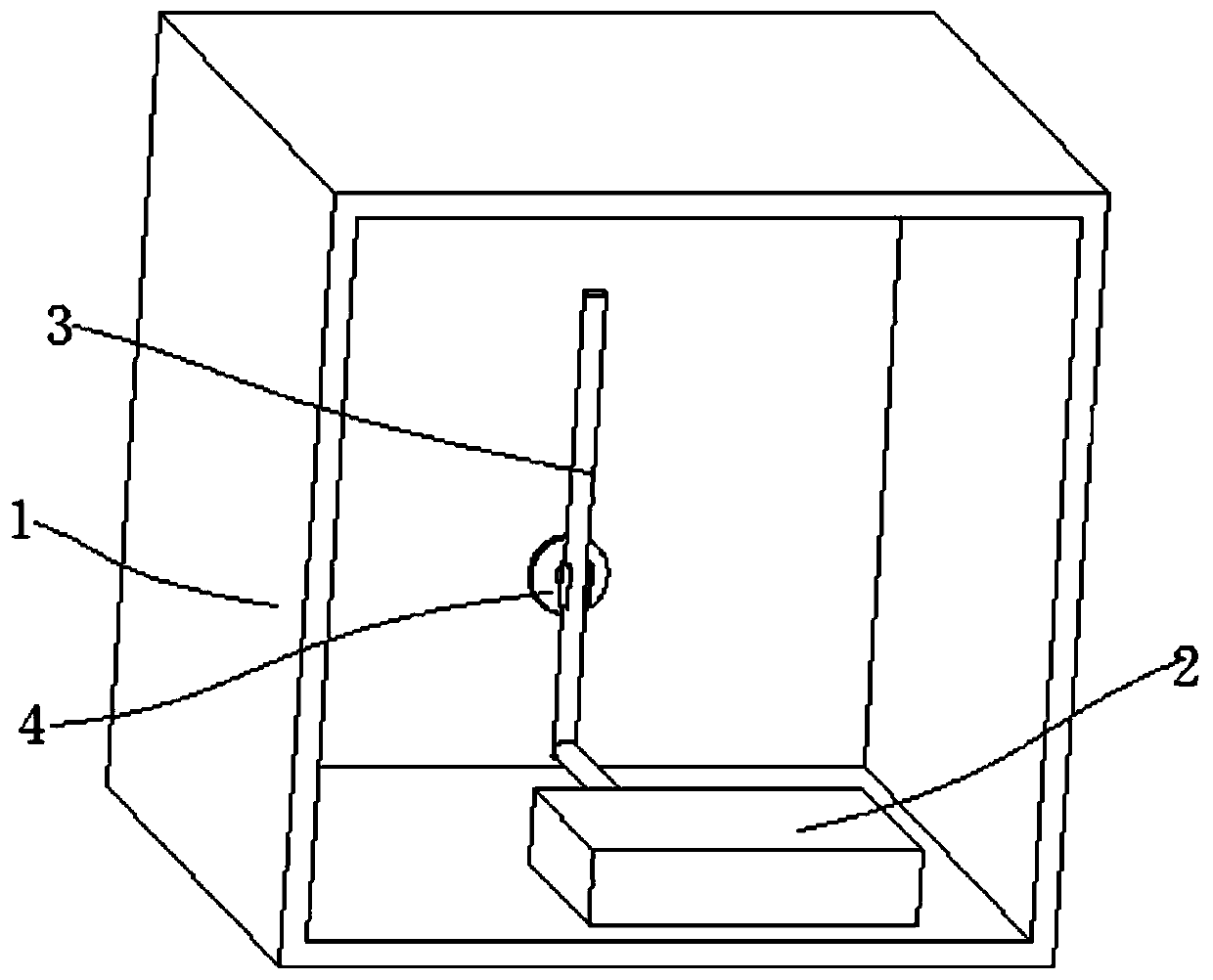
[0022] The embodiment of the invention discloses an electronic equipment module to effectively solve the problem of poor wiring of the electronic equipment.

[0023] The following will clearly and completely describe the technical solutions in the embodiments of the present invention with reference to the accompanying drawings in the embodiments of the present invention. Obviously, the described embodiments are only some, not all, embodiments of the present invention. Based on the embodiments of the present invention, all other embodiments obtained by persons of ordinary skill in the art without making creative efforts belong to the protection scope of the present invention.

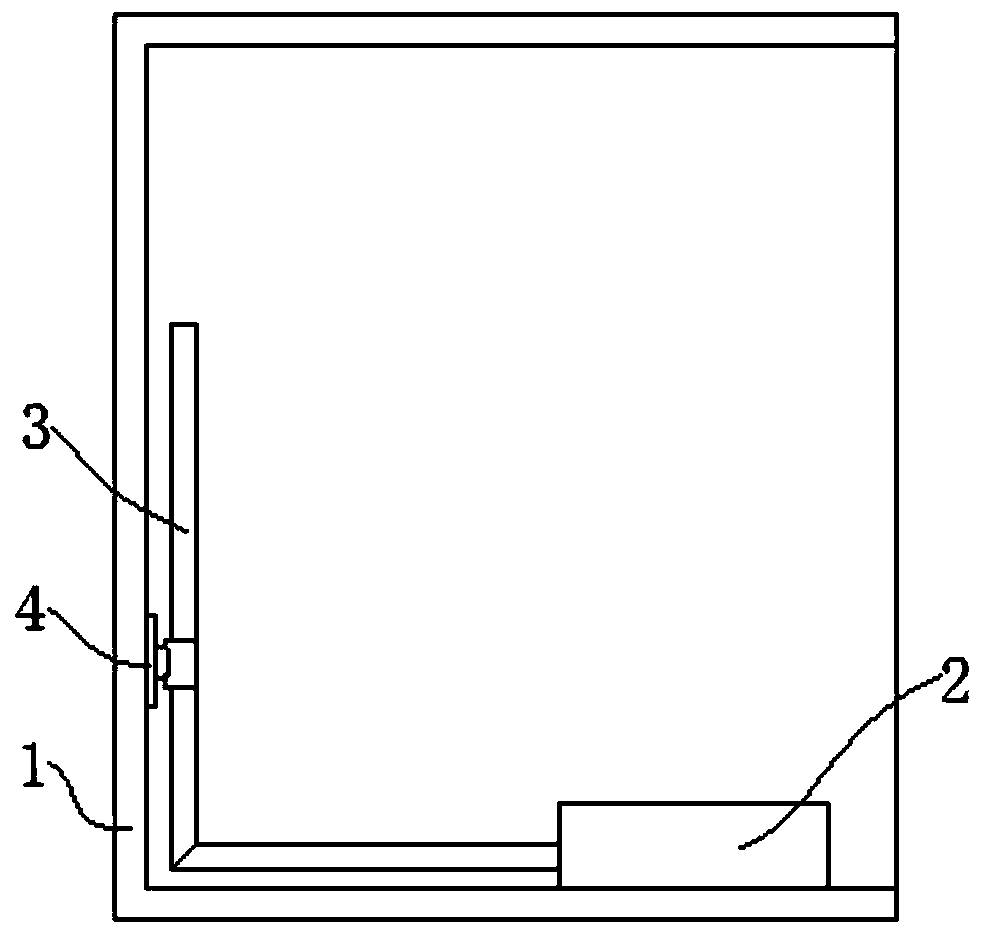
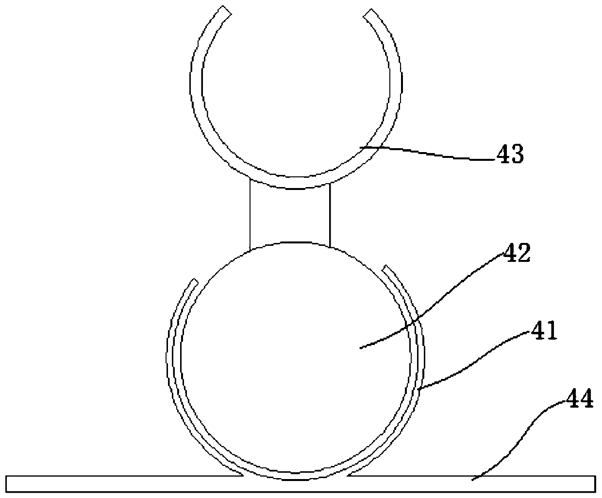
[0024] see Figure 1-Figure 3 , figure 1 A schematic structural diagram of an electronic device module provided by an embodiment of the present invention; figure 2 A schematic diagram of the side structure of the electronic equipment module provided by the embodiment of the present invention; image ...


PUM


Abstract

The invention discloses an electronic equipment module which comprises a bearing body, electronic equipment arranged on the bearing body, a wire body connected with the electronic equipment, and a plurality of wire clamping buckles which are sequentially arranged along the wire body, each wire clamping buckle comprises a base part adhered to the bearing body and a buckle part connected with the base part, and the buckle part can lock the wire body. The wire clamping buckle is adhered to the wire body to make the dismounting convenient, the surface of the bearing body is not damaged in the dismounting process, so that the wiring position of the wire body can be freely replaced at any time, the existing wire body wiring can be conveniently re-planned when other electronic devices are re-installed, and meanwhile, the corresponding wire body can be conveniently dismounted when the existing electronic equipment is dismounted. And the wire body is locked, so that the wire body is convenientto disassemble or assemble.

Description

technical field [0001] The present invention relates to the field of electronic technology, and more specifically, to an electronic equipment module. Background technique [0002] At present, the wide use of various electrical appliances makes more and more wires, and there are higher requirements for the convenience and aesthetics of wire fixing. At present, there are mainly three ways to fix the wiring on the equipment body: one is to fix the wire through a special mechanism design. The disadvantage of this fixing method is that it needs to be specially designed. Once the wiring is changed, the mechanism design must also be changed. , and the cost will be higher; the other is to semi-fix the wire with cable ties, the disadvantage is that the wire cannot be completely fixed, and it is basically a one-time use; the other is to fix the wire through a special cable management box, the disadvantage is that the cost is high , and disassembly and assembly are more troublesome. ...

Claims


Application Information

Patent Timeline
Patent Type & Authority Applications(China)
IPC IPC(8): H05K7/02
CPCH05K7/023H05K7/026
Inventor 黄朋太
Owner INSPUR BUSINESS MACHINE CO LTD
Learn More