Device and method for running casing operation by using turnbuckle faucet

A faucet and casing technology, which is applied to drilling equipment and methods, earthwork drilling, drilling equipment, etc., can solve the problems of untimely circulation of mud and rotating casing when casing is run, so as to improve production efficiency and safety, The effect of increasing the success rate

Active Publication Date: 2022-01-25
INST OF SINOPEC OILFIELD EQUIP CORP +1
View PDF4 Cites 0 Cited by
  • Summary
  • Abstract
  • Description
  • Claims
  • Application Information

AI Technical Summary

Problems solved by technology

[0011] Another object of the present invention is to provide a device for running casing by using a turnbuckle faucet. For drilling rigs that are not equipped with top drive, through the cooperative setting of the turnbuckle faucet and the casing clamping head, the problem of casing running in existing devices can be solved. The pipe does not circulate the mud in time and the problem of rotating the casing

Method used


Image

  • Device and method for running casing operation by using turnbuckle faucet
  • Device and method for running casing operation by using turnbuckle faucet
  • Device and method for running casing operation by using turnbuckle faucet

Examples


Embodiment 1

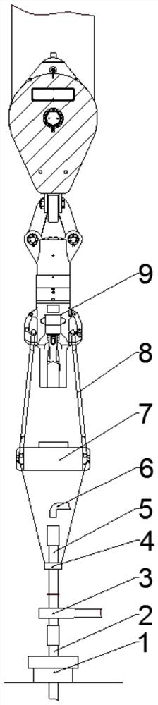
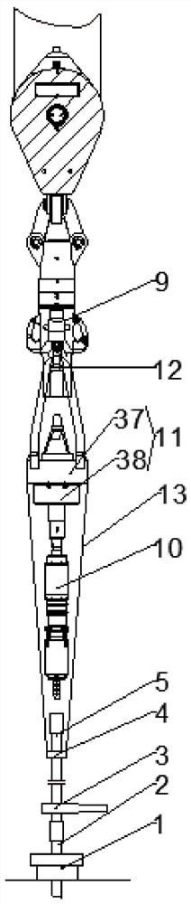
[0057] The device for running the casing by using the turnbuckle faucet, including: the main winch, the big hook 9 driven by the main winch to move up and down, the main hook body 12, the drill floor slips 1 on the drill floor, hydraulic casing tongs 3. It also includes: a turnbuckle faucet 11 suspended on the main hook body 12 of the big hook 9, a sleeve clamping head 10 detachably fixed to the bottom end of the turnbuckle faucet 11, and a wire rope 13 suspended on the bottom of the turnbuckle faucet. The casing elevator 4 on the turnbuckle faucet 11 and below the turnbuckle faucet 11 and the casing clamping head 10, wherein the turnbuckle faucet 11 includes a common faucet 37 and is detachable from the common faucet 37 The provided spinner 38, the common faucet 37 can specifically be an XSL225 type faucet, and the spinner 38 is a 225 spinner;

[0058] The operation method of the device using the turnbuckle faucet for casing operation includes the following steps:

[0059] S...

Embodiment 2

[0070] The device for running the casing by using the turnbuckle faucet, including: the main winch, the big hook 9 driven by the main winch to move up and down, the main hook body 12, the drill floor slip 1 arranged on the drill floor, and also includes: suspension The turnbuckle faucet 11 on the main hook body 12 of the big hook 9, the casing clamping head 10 detachably connected to the bottom end of the turnbuckle faucet 11, is suspended on the turnbuckle faucet 11 through a wire rope 13 And the casing elevator 4 and hydraulic casing tongs 3 located below the turnbuckle faucet 11 and the casing clamping head 10;

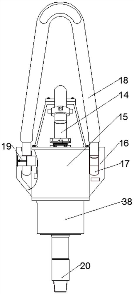
[0071] Wherein, the turnbuckle faucet 11 includes an ordinary faucet 37 and a turnbuckle 38 detachably arranged with the ordinary faucet 37, the gooseneck of the turnbuckle faucet 11 is connected with the water hose of the mud circulation system, and the ordinary faucet 37 includes a basic The function is similar to the faucet body 14 of the XSL225 type faucet, the...


PUM


Abstract

The invention discloses a device for casing running operation by using a turnbuckle faucet, which comprises a main hook body of a big hook and a drill floor slip provided on the drill floor, and is characterized in that it also includes: The turnbuckle faucet on the hook body, the casing clamping head detachably fixed to the bottom end of the turnbuckle faucet, is suspended on the turnbuckle faucet through a wire rope and is located between the turnbuckle faucet and the casing clamp. A casing elevator and a hydraulic casing clamp under the holding head, wherein the turnbuckle faucet includes a common faucet and a spinner that is detachably arranged with the common faucet. Aiming at the drilling rig without top drive, the invention can rotate the casing string and circulate the mud in time according to the needs through the cooperative setting of the turnbuckle faucet and the casing clamping head, which improves the production efficiency and safety, and improves the success of casing running. rate beneficial effect.

Description

technical field [0001] The invention relates to the technical field of petroleum cementing. More specifically, the present invention relates to a device and method for casing running operation using a turnbuckle faucet. Background technique [0002] According to the design requirements of the drilling well body structure, after each stage of drilling, in order to strengthen the well wall and isolate the oil, water and gas layers, it is necessary to run casing and carry out cementing operations to ensure safe drilling and reasonable oil and gas production. . Casing is the operation of connecting each casing with a length of about 10 meters together one by one to form a casing string, and lowering it to the predetermined depth of the open hole according to the design requirements; the cementing operation is the operation between the casing string and the Cement slurry is injected between the well walls, and the casing string is fixed on the well walls after the cement slurry...

Claims


Application Information

Patent Timeline
Patent Type & Authority Patents(China)
IPC IPC(8): E21B7/20
CPCE21B7/20
Inventor 黎爱军周斌余长柏信石玉高海平李大彬
Owner INST OF SINOPEC OILFIELD EQUIP CORP
Why Eureka
Try Eureka