
Pulsar signal phase delay estimation method considering spacecraft orbit dynamic effect

A technique for orbit dynamics and delay estimation, applied in navigation calculation tools, astronomical navigation, etc., can solve the problems of no solution, error natural robustness, and unresolved problems such as pulse phase delay estimation of on-orbit pulsar signals, to achieve Easy to implement, avoid the amount of computation, and highly operable

Active Publication Date: 2020-03-31
合肥名龙电子科技有限公司
View PDF9 Cites 8 Cited by
  • Summary
  • Abstract
  • Description
  • Claims
  • Application Information

AI Technical Summary

Problems solved by technology

[0004] Document 1 (Liu Jin, Zeng Xianwu, Fang Jiancheng, Ning Xiaolin. Time-of-arrival compensation of pulsar pulses based on starlight Doppler [J]. 2014, 42(1): 129-132.) By introducing starlight Doppler Measure the information to correct the pulse arrival time, but this method does not consider the influence of orbital dynamic motion on the photon arrival phase in essence, but only models the Doppler effect as the influence on the overall pulse arrival time, and introduces auxiliary information to achieved goals,
[0005] The patent application No. 201510491219.0 proposes a dynamic pulsar signal processing method based on orbital dynamics, but this method ignores various dynamic delay effects of photons propagating in large-scale space in modeling, such as Sharpy Lowe delay, Einstein delay, etc., and this method uses two-dimensional maximum likelihood to jointly estimate the pulse phase and Doppler frequency, which faces a huge amount of computation, and there is no way to use photon sequence period folding to be naturally robust to frequency estimation errors sex
In summary, this method has not yet solved the problem of pulse phase delay estimation of on-orbit pulsar signals.

Method used


Image

  • Pulsar signal phase delay estimation method considering spacecraft orbit dynamic effect
  • Pulsar signal phase delay estimation method considering spacecraft orbit dynamic effect
  • Pulsar signal phase delay estimation method considering spacecraft orbit dynamic effect

Examples


Embodiment Construction

[0033] The present invention will be further described in detail below with reference to the drawings and specific embodiments.

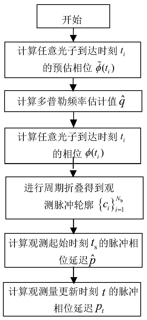
[0034] In this embodiment, a deep space probe in the cruise section is taken as an example. It is assumed that the spacecraft is in the observation period [t s ,t e ] The arrival time sequence of photons detected within is The phase delay estimation method includes the following steps when using the proposed phase delay estimation method of on-orbit pulsar signals considering the dynamic effects of the spacecraft orbit. figure 1 with figure 2 Shown:

[0035] Step (1), it is helpful to estimate the orbit information to calculate the photon arrival time t i Corresponding estimated phase value

[0036] Knowing the estimated position and velocity of the spacecraft at the initial moment of observation, using the spacecraft’s orbital dynamics model to propagate the orbit, the spacecraft’s i The estimated position of the time relative to the center of mass SS...


PUM


Abstract

The invention discloses a pulsar signal phase delay estimation method considering a spacecraft orbit dynamic effect. The method comprises the following steps: firstly, obtaining an estimated positionand speed of a spacecraft at any photon arrival moment by utilizing an orbit kinetic model propagating orbit, obtaining an estimated phase value at any photon arrival moment through large-scale time conversion and a phase model at an SSB, and estimating Doppler frequency shift introduced by an initial speed error of the spacecraft; and after Doppler frequency shift is corrected, obtaining an observation pulse profile through periodic folding, estimating phase delay introduced by an initial position error, and obtaining the phase delay of the spacecraft at the observed quantity updating momentby adding the phase delay introduced by the initial position error and accumulated phase delay introduced by Doppler frequency. According to the method, the influence of on-orbit motion characteristics of the spacecraft on the X-ray pulsar signals does not need to be corrected under the assumption that the initial speed of the spacecraft is known, the huge operand of joint search Doppler frequencyand phase delay is avoided, operability is high, and implementation is easy.

Description

Technical field [0001] The invention belongs to the field of spacecraft autonomous navigation, and particularly relates to an on-orbit pulsar signal phase delay estimation method considering the spacecraft orbit dynamic effect. Background technique [0002] X-ray pulsar navigation is an emerging autonomous navigation method for spacecraft. Its navigation accuracy is not affected by the relative position of the spacecraft and celestial bodies. It is the most promising deep space navigation method in the future. X-ray pulsar navigation uses X-ray photon signals emitted by pulsars for navigation. The spacecraft compares the pulsar signals observed in orbit with the standard signal model at the center of mass of the solar system (SSB) to obtain the basic observations for navigation. , That is, the pulse phase delay between the observed pulsar signal and the standard signal model. [0003] The estimation accuracy of pulse phase delay restricts the accuracy of pulsar navigation. Pulsar...

Claims


Application Information

Patent Timeline
IPC IPC(8): G01C21/02G01C21/20
CPCG01C21/02G01C21/20
Inventor 薛梦凡彭冬亮郭云飞申屠晗骆吉安陈志坤
Owner 合肥名龙电子科技有限公司
Learn More