
Experimental device and experimental method for ice accumulation and transportation in front of gate under condition of free outflow of water flow

An experimental device and experimental technology, which is applied in the direction of measuring device, fluid dynamics test, machine/structural component test, etc., can solve the problems of device cost, site cost, poor effect of simulation experiment, harshness, high cost of water resources, etc.

Active Publication Date: 2020-03-31
SICHUAN UNIV
View PDF6 Cites 2 Cited by
  • Summary
  • Abstract
  • Description
  • Claims
  • Application Information

AI Technical Summary

Problems solved by technology

However, the experimental device disclosed in this paper is an existing straight-walled glass water tank, and its size and length are very large (2000×50×90) cm, so it has relatively strict requirements for its test site, and because of The volume of the water tank is large, and the cost of water resources invested when starting the experiment is usually large
[0007] As for the accumulation and transport of ice under the condition of free flow from the bottom hole of the flat gate, which is common in open channel water flow, the simulation experiment device usually needs to ensure that the water flow reaches a uniform speed state before the simulated ice cubes are added, and the ice cubes and ice cubes are separated after adding. The simulation experiment is carried out under the premise of the same water flow velocity, so the existing simulation experiment equipment is mostly modified by other research projects as in the above paper, and the equipment cost, especially the site cost and the simulation experiment effect are usually not good

Method used


Image

  • Experimental device and experimental method for ice accumulation and transportation in front of gate under condition of free outflow of water flow
  • Experimental device and experimental method for ice accumulation and transportation in front of gate under condition of free outflow of water flow
  • Experimental device and experimental method for ice accumulation and transportation in front of gate under condition of free outflow of water flow

Examples


Embodiment 1

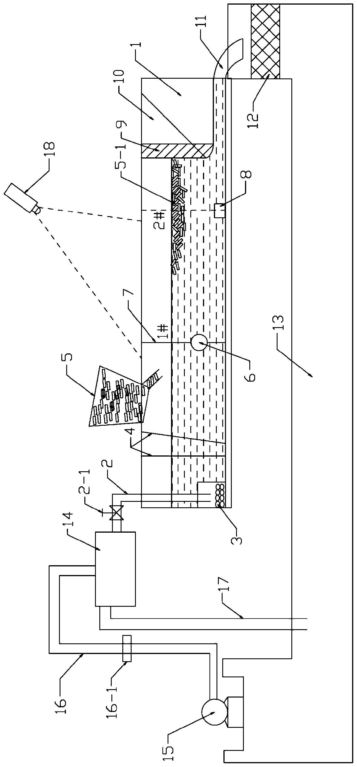
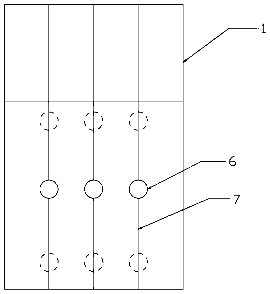
[0071] An experimental device for ice accumulation and transportation in front of the sluice under the condition of free flow of water flow, the real object is as follows figure 1 As shown, the schematic diagram is as figure 2 As shown, it includes a water inlet circulation system and an experimental water tank system. The experimental water tank system includes a rectangular parallelepiped experimental water tank 1 with a specification of 15m×0.4m×1.0m, and an experimental water tank water inlet pipe 2, Water inlet energy dissipation device 3, water flow energy dissipation device 4, simulated ice cube delivery device 5, water flow section monitoring device, gate 9, experimental water tank outlet pipe 11; the water inlet circulation system includes a circulating water tank 13, a simulated ice cube collection network 12. Water pump 15, and buffer tank 14;

[0072] The water inlet pipe 2 of the experimental water tank is arranged at the end of one end in the length direction o...

Embodiment 2

[0100] An experimental device for ice accumulation and transportation in front of the sluice under the condition of free flow of water, including a water inlet circulation system and an experimental water tank system. In the length direction of the experimental water tank, the water inlet pipe of the experimental water tank, the water inlet energy dissipation device, the water flow energy dissipation device, the simulated ice cube feeding device, the water flow section monitoring device, the gate, and the water outlet pipe of the experimental water tank are successively arranged; the water inlet circulation system includes Circulating tank, simulated ice collection net, water pump, and buffer tank;

[0101] The water inlet pipe of the experimental water tank is set at one end of the experimental water tank in the length direction, and is set at the center of the experimental water tank in the width direction. At 0.25m from the bottom of the water tank, the water inlet and ener...

Embodiment 3

[0112]An experimental device for ice accumulation and transportation in front of the sluice under the condition of free flow of water, including a water inlet circulation system and an experimental water tank system. In the length direction of the experimental water tank, the water inlet pipe of the experimental water tank, the water inlet energy dissipation device, the water flow energy dissipation device, the simulated ice cube feeding device, the water flow section monitoring device, the gate, and the water outlet pipe of the experimental water tank are successively arranged; the water inlet circulation system includes Circulating tank, simulated ice collection net, water pump, and buffer tank;

[0113] The water inlet pipes of the experimental water tank are arranged at one end of the experimental water tank in the length direction, and are distributed in parallel at a distance of 0.1 m along the width direction of the experimental water tank. At 0.35m from the bottom of t...


PUM


Abstract

The invention provides an experimental device and an experimental method for ice accumulation and transportation in front of a gate under the condition of free outflow of water flow. The experimentaldevice comprises a water inlet circulating system and an experimental water tank system, the experiment water tank system comprises a cuboid experiment water tank with the specification of (14-16)m*(0.4-0.6)m*(0.7-1.0)m, and an experiment water tank water inlet pipe, a water inlet energy dissipation device, a water flow energy dissipation device, a simulated ice block putting device, a water flowsection monitoring device, a gate and an experiment water tank water outlet pipe are sequentially arranged in the length direction of the experiment water tank. The experimental device is specially designed for experiments of ice accumulation and transportation in front of a gate under the condition of free outflow of water flow, and has the advantages of reasonable structure, small occupied areaand lower device and experimental cost, the experimental method is matched with the experimental device, optimization is performed on the basis of the existing experimental method, and the time for asingle experiment is shortened.

Description

technical field [0001] The invention belongs to the technical field of water conservancy and hydropower engineering, and specifically relates to an experimental device for ice accumulation and transportation in front of a sluice under the condition of free flow of water flow and an experimental method thereof, especially suitable for the condition of free flow of ice from the bottom hole of a flat gate in an open channel. The experimental device and experimental method of accumulation and transportation. Background technique [0002] The geographical distribution of my country's water resources is extremely unbalanced, 80% of which are distributed in the southwest region, and the time distribution is also quite different. The runoff of three months in the wet season can account for more than 60% of the annual runoff. In order to change the unbalanced distribution of water resources in time and space, the construction of long-distance and large-flow water diversion projects i...

Claims


Application Information

Patent Timeline
Patent Type & Authority Applications(China)
IPC IPC(8): G01M10/00
CPCG01M10/00
Inventor 脱友才梁乃生邓云李嘉杨小倩贾云霄
Owner SICHUAN UNIV
Learn More