Imaging optical system, projection display device, and imaging apparatus
A technology of imaging optics and optical axis, which is applied in the fields of imaging optical systems, projection display devices and camera devices, can solve the problems of miniaturization, enlargement, large lens diameter, etc., and achieve the effect of wide viewing angle
- Summary
- Abstract
- Description
- Claims
- Application Information
AI Technical Summary
Problems solved by technology
Method used
Image
Examples
Embodiment 1
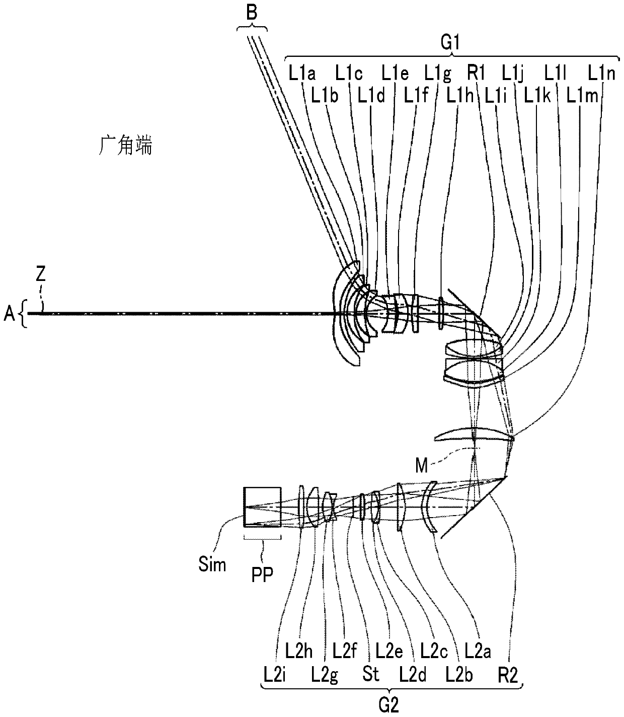
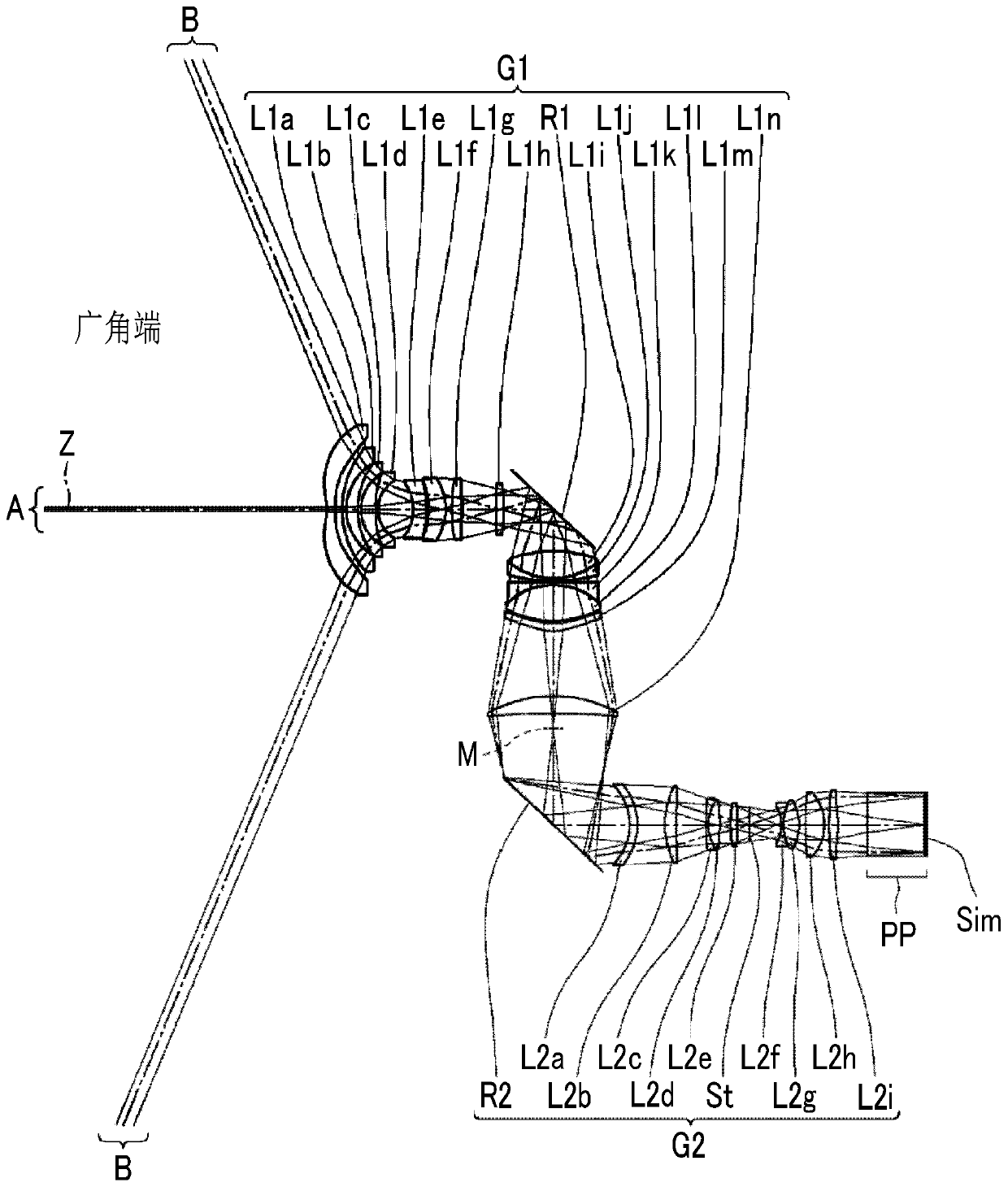
[0089] A cross-sectional view showing the structure of the imaging optical system of Example 1 is shown in figure 1 , a cross-sectional view showing a modified example of the imaging optical system of Example 1 is shown in figure 2 . figure 1 The graphical method of is as described above, and for figure 2 also with figure 1 The same illustration method, so some repeated descriptions are omitted here. In addition, the illustration method is basically the same as that of Examples 2 to 4.
[0090] figure 1 The imaging optical system of the illustrated embodiment 1 includes the first lens group G1 and the second lens group G2 in sequence along the optical axis Z from the magnification side to the reduction side, and the first lens group G1 and the second lens group G2 on the optical axis Z are A relay-type imaging optical system that forms an intermediate image M between the 2 lens groups G2.
[0091] The first lens group G1 is composed of 14 lenses of lenses L1a to L1n, a...
Embodiment 2
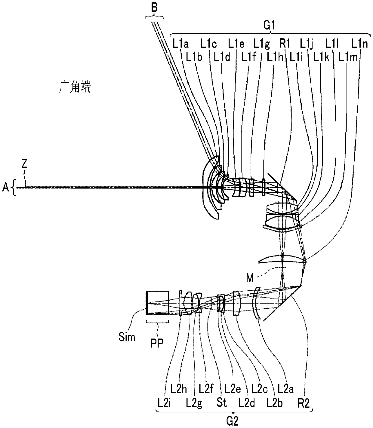
[0122] Next, the imaging optical system of Example 2 will be described. A cross-sectional view showing the structure of the imaging optical system of Example 2 is shown in image 3 , a cross-sectional view showing a modified example of the imaging optical system of Example 2 is shown in Figure 4 . The configuration of the imaging optical system of Example 2 is the same as that of the imaging optical system of Example 1. In addition, the basic lens data of the imaging optical system of Example 2 are shown in Table 5, the data related to the specifications are shown in Table 6, and the data related to the variable surface distance are shown in Table 7, and the data related to the aspheric coefficient The data of is shown in Table 8, and each aberration diagram is shown in Figure 10 .
[0123] [table 5]
[0124] Embodiment 2 Lens data (n, ν are d lines)
[0125] face number radius of curvature face spacing n ν *1 -5.9079 1.0788 1.53158 55.08 *...
Embodiment 3
[0136] Next, the imaging optical system of Example 3 will be described. A cross-sectional view showing the structure of the imaging optical system of Example 3 is shown in Figure 5 , a cross-sectional view showing a modified example of the imaging optical system of Example 3 is shown in Image 6 . In the second lens group G2, the first moving lens group is composed of two lenses L2a to L2b, and the second moving lens group is composed of six lenses L2c to L2h. In addition, the imaging of Embodiment 3 The structure of the optical system is the same as that of the imaging optical system of Embodiment 1. In addition, the basic lens data of the imaging optical system of Example 3 are shown in Table 9, the data related to the specifications are shown in Table 10, the data related to the variable surface distance are shown in Table 11, and the data related to the aspheric surface coefficient are shown in Table 11. The data of is shown in Table 12, and each aberration diagram is ...
PUM
 Abstract
Description
Claims
Application Information
 - R&D
- Intellectual Property
- Life Sciences
- Materials
- Tech Scout
- Unparalleled Data Quality
- Higher Quality Content
- 60% Fewer Hallucinations
Browse by: Latest US Patents, China's latest patents, Technical Efficacy Thesaurus, Application Domain, Technology Topic, Popular Technical Reports.
© 2025 PatSnap. All rights reserved.Legal|Privacy policy|Modern Slavery Act Transparency Statement|Sitemap|About US| Contact US: help@patsnap.com


