Method for improving performance of gas turbine

A technology of gas turbine and performance, which is applied in the directions of gas turbine device, combustion method, engine function, etc., can solve the problems of high disassembly and combination, undesired, cost, etc.

Active Publication Date: 2020-03-31
西门子能源全球有限两合公司
View PDF14 Cites 1 Cited by
  • Summary
  • Abstract
  • Description
  • Claims
  • Application Information

AI Technical Summary

Problems solved by technology

However, this dismantling of the rotor is associated with very high effort and is correspondingly undesirable

Method used


Image

  • Method for improving performance of gas turbine
  • Method for improving performance of gas turbine
  • Method for improving performance of gas turbine

Examples


Embodiment Construction

[0027] In the following, the same reference numerals denote the same or similar components.

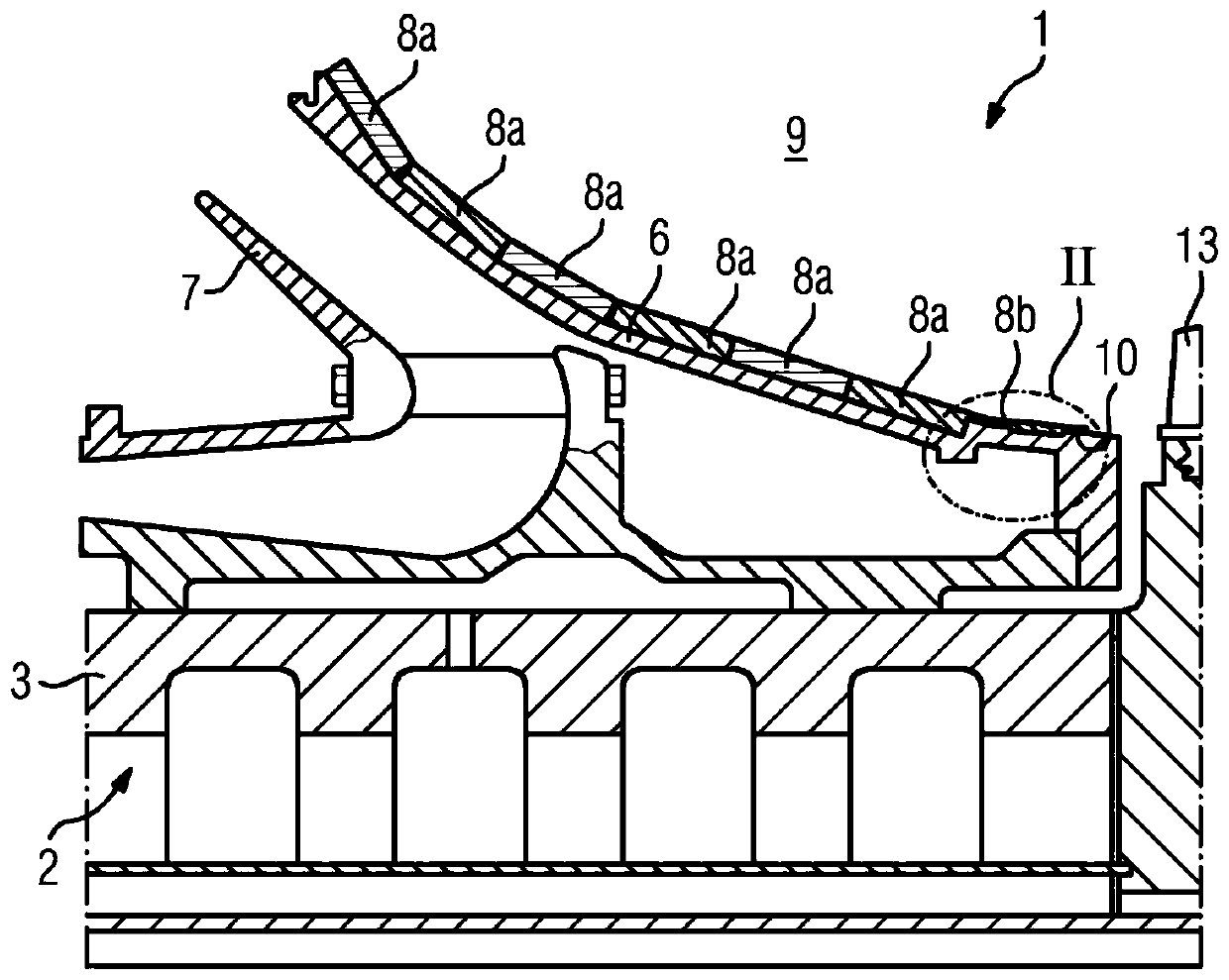
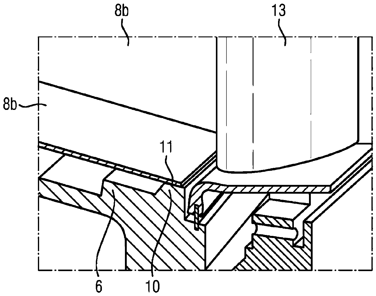
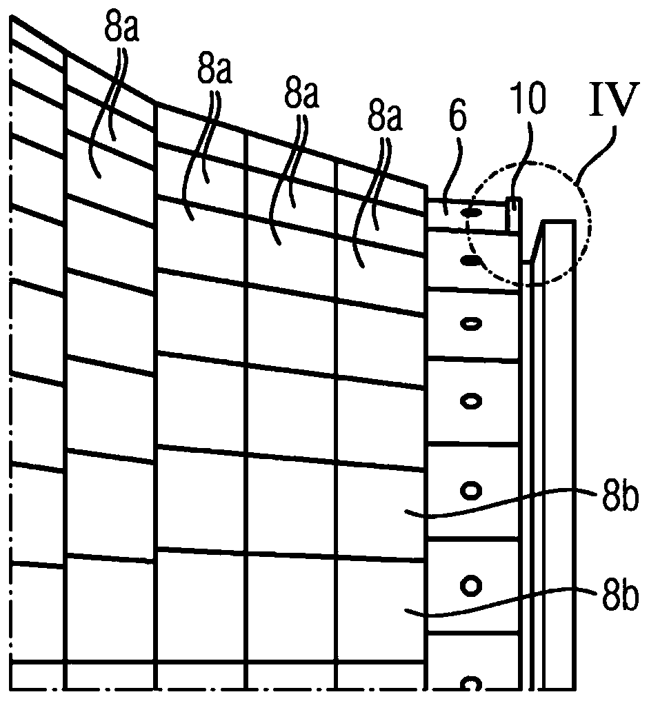
[0028] The gas turbine 1 comprises a rotor 2 having a shaft 3 on which is arranged or fastened a plurality of axially adjacent rows 4 of turbine rotor blades of the turbine region of the gas turbine 1 and a plurality of adjacent rows of the compressor region. Set of compressor rotor blade rows 5. Furthermore, the gas turbine 1 comprises a funnel-shaped hub 6 extending around the shaft 3 , which is arranged between the turbine region and the compressor region and decreases in diameter in the direction of the turbine rotor blade row 4 and thus in the downstream direction. Small. The hub 6 is oriented concentrically with respect to the shaft 3 with a radial annular gap and is held stationary on the housing 7 of the gas turbine 1 so that it does not rotate with the shaft 3 . A plurality of annular rows of heat shielding elements 8a, 8b are fastened axially adjacent to the outer side of ...


PUM


Abstract

The invention relates to a method for improving the performance of a gas turbine (1), in which a hub (6) annually surrounding a rotor (2) is machined when the rotor (2) is in the non-stacked state andhot shield elements that are arranged on the hub (6) are exchanged.

Description

technical field [0001] The present invention relates to a method for improving the performance of a gas turbine having: a combustion chamber; a rotor comprising a shaft and a plurality of rows of turbine rotor blades disposed axially adjacent to the shaft; and a hub, the The hub is arranged upstream of the row of turbine rotor blades and extends around the shaft and is funnel-shaped, on which are fixed axially adjacent rows of heat shielding elements which cover the radial direction of the hub in isolation. a large part of the outwardly directed face and delimiting a part of the boundary of the combustion chamber, wherein the heat shield elements arranged in the downstream direction in the last row are arranged adjacent to the radially outwardly projecting, circumferentially formed hub projections, And it is cooled via cooling air holes formed in the hub. Background technique [0002] Gas turbines of the type mentioned at the outset are already known in the prior art. Here...

Claims


Application Information

Patent Timeline
Patent Type & Authority Applications(China)
IPC IPC(8): F01D9/02F02C3/16F02C3/14F02C7/12F23R3/00
CPCF05D2240/35F01D9/023F02C3/14F02C7/12F23R3/007F05D2230/80F05D2240/15F02C7/18F05D2230/10F05D2260/201F01D25/285
Inventor 里克·吉塞尔扬尼科·吕普费特贝恩德·沃纳曼
Owner 西门子能源全球有限两合公司
Why Eureka
Try Eureka