
Respiratory tract cleaning device

A technology for cleaning device and airway, applied in the field of airway cleaning, can solve the problems of inconvenient operation, increase the risk of medical accident, equipment damage, etc., and achieve the effect of being convenient for multiple use, reducing the risk of medical accident, and being convenient for disassembly and assembly.

Inactive Publication Date: 2020-04-03
张言春
View PDF6 Cites 0 Cited by
  • Summary
  • Abstract
  • Description
  • Claims
  • Application Information

AI Technical Summary

Problems solved by technology

[0002] The respiratory tract is the channel through which the airflow passes when the lungs breathe. The respiratory tract is divided into upper and lower parts: the nose, pharynx, and larynx are collectively called the upper respiratory tract, and the trachea, bronchi and lung organs are collectively called the lower respiratory tract, or the tracheal tree. , The tracheal tree is gradually complicated with the evolution of animals. Foreign bodies in the trachea are relatively common accidental emergencies, which need to be removed in time. Clinically, the method of respiratory tract intervention is often used to remove foreign bodies under direct vision. Doctors need to hold a laser in one hand. The probe is cleaned with a cleaning device in one hand. However, the existing device is not convenient for the doctor to operate. At the same time, it cannot support the patient's oral cavity during the cleaning process. Opening the mouth for a long time will easily cause fatigue, causing the patient to close the mouth, which is easy. Damage to the device while increasing the risk of medical malpractice

Method used


Image

  • Respiratory tract cleaning device
  • Respiratory tract cleaning device
  • Respiratory tract cleaning device

Examples


Embodiment Construction

[0018] The following will clearly and completely describe the technical solutions in the embodiments of the present invention with reference to the accompanying drawings in the embodiments of the present invention. Obviously, the described embodiments are only some, not all, embodiments of the present invention. Based on the embodiments of the present invention, all other embodiments obtained by persons of ordinary skill in the art without making creative efforts belong to the protection scope of the present invention.

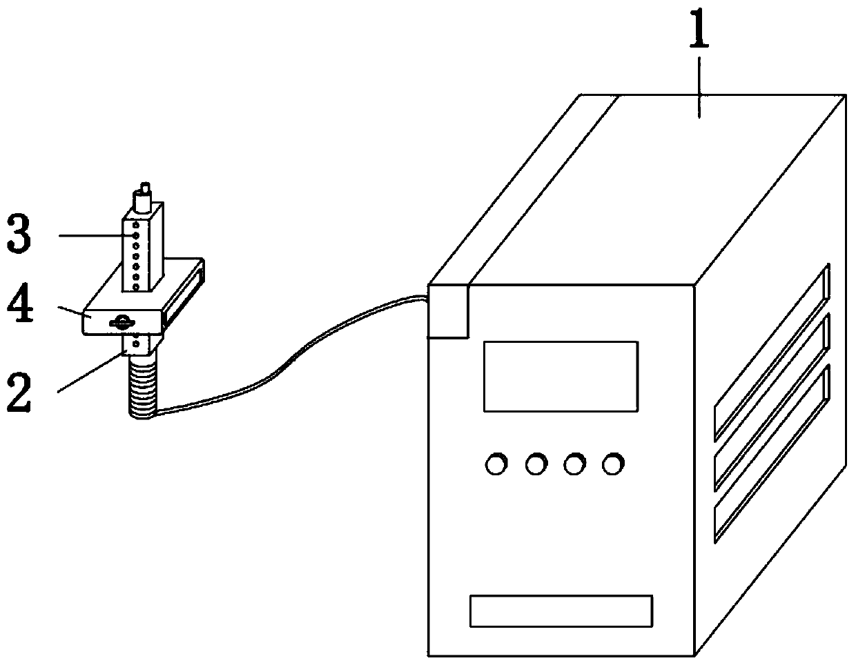
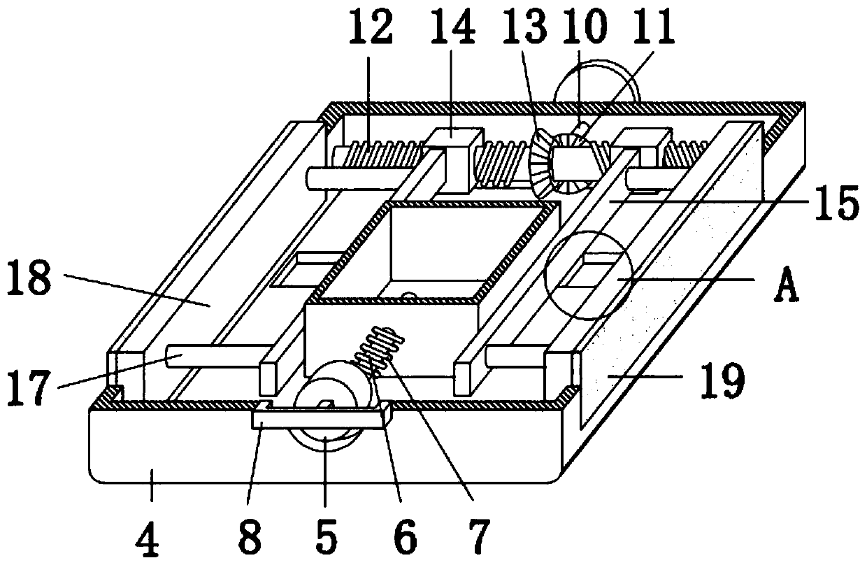
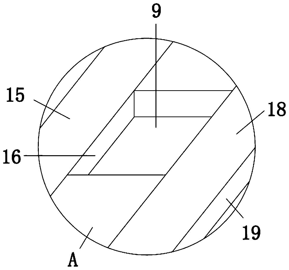
[0019] see Figure 1-3 , the present invention provides a technical solution: a respiratory cleaning device, comprising a cleaning device main body 1 and a cleaning probe main body 2, the right side of the cleaning device main body 1 is connected with a cleaning probe main body 2 through a connecting pipe, and the front of the outer wall of the cleaning probe main body 2 The side is continuously provided with a card slot 3 from top to bottom, the outer wall of...


PUM


Abstract

The invention discloses a respiratory tract cleaning device. The device comprise a cleaning device main body and a cleaning probe main body, the right side of the cleaning device main body is connected with the cleaning probe main body through a connecting pipe, the outer wall of the cleaning probe main body is sleeved with a rectangular box, the front side of the rectangular box is inserted witha cylinder, the rear side of the cylinder is clamped with an inserting rod, the outer wall of the inserting rod is sleeved with a spring, the rear side of the inner cavity of the rectangular box is connected with a screw rod through a bearing in the left and right directions, and the outer wall of the screw rod is provided with an expansion structure. By pulling the cylinder to the front side, thespring can be stretched, the inserting rod can be separated from the inner cavity of the a clamping groove, the rectangular box can be conveniently disassembled, time and labor are saved, the deviceis convenient for sterilization treatment and for multiple uses, the mouth can be supported by a retractable structure, the mouth of a patient can be prevented from closing in the cleaning process, mouth closing results in damage to the device, the risk of medical accidents can be reduced at the same time, and a bracket can be adjusted according to patients of different ages so as to make the patients more comfortable.

Description

technical field [0001] The invention relates to the technical field of airway cleaning, in particular to an airway cleaning device. Background technique [0002] The respiratory tract is the channel through which the airflow passes when the lungs breathe. The respiratory tract is divided into upper and lower parts: the nose, pharynx, and larynx are collectively called the upper respiratory tract, and the trachea, bronchi and lung organs are collectively called the lower respiratory tract, or the tracheal tree. , The tracheal tree is gradually complicated with the evolution of animals. Foreign bodies in the trachea are relatively common accidental emergencies, which need to be removed in time. Clinically, the method of respiratory tract intervention is often used to remove foreign bodies under direct vision. Doctors need to hold a laser in one hand. The probe is cleaned with a cleaning device in one hand. However, the existing device is not convenient for the doctor to operat...

Claims


Application Information

Patent Timeline
Patent Type & Authority Applications(China)
IPC IPC(8): A61B17/50A61B90/16
CPCA61B17/50A61B90/16
Inventor 张言春
Owner 张言春
Learn More