
Finned pipe type heat exchanger pipe inserting mechanism

A finned tube heat exchanger technology, applied in the field of highly automated production equipment, can solve the problems of many pipelines, low processing efficiency, uncontrollable, etc., and achieve the effects of avoiding manual operation, improving production efficiency, and low processing efficiency

Inactive Publication Date: 2020-04-03
SHANDONG UNIV +1
View PDF5 Cites 8 Cited by
  • Summary
  • Abstract
  • Description
  • Claims
  • Application Information

AI Technical Summary

Problems solved by technology

[0003] Due to the large number of fins in the heat exchanger, each fin is relatively thin, and the diameter of the tube to be intubated is small and there are many pipelines. pieces cause damage
In the prior art, the assembly of the heat exchanger is done manually, and the tubes are manually taken out one by one, and then inserted into the shaped heat exchanger fins one by one. This working method leads to low efficiency of the entire intubation process and low processing efficiency. , and it is uncontrollable, and it is easy to cause damage to the heat dissipation tube (U-shaped tube), but there is no assembly equipment that can complete the automatic insertion of the heat exchanger in the prior art

Method used


Image

  • Finned pipe type heat exchanger pipe inserting mechanism
  • Finned pipe type heat exchanger pipe inserting mechanism
  • Finned pipe type heat exchanger pipe inserting mechanism

Examples


Embodiment Construction

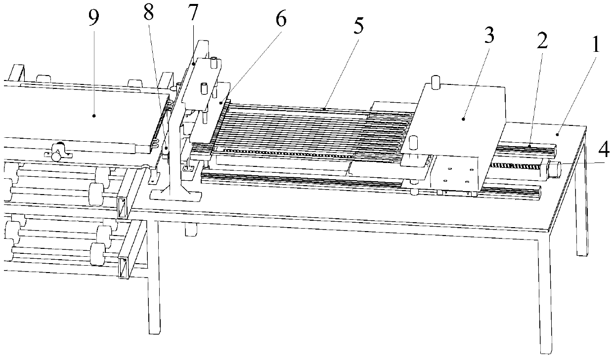
[0023] The invention provides an automatic intubation device, which is particularly suitable for the intubation of heat pipes with closely arranged heat sinks, for example, it is suitable for the intubation process of heat pipes in the assembly and production process of finned tube heat exchangers.

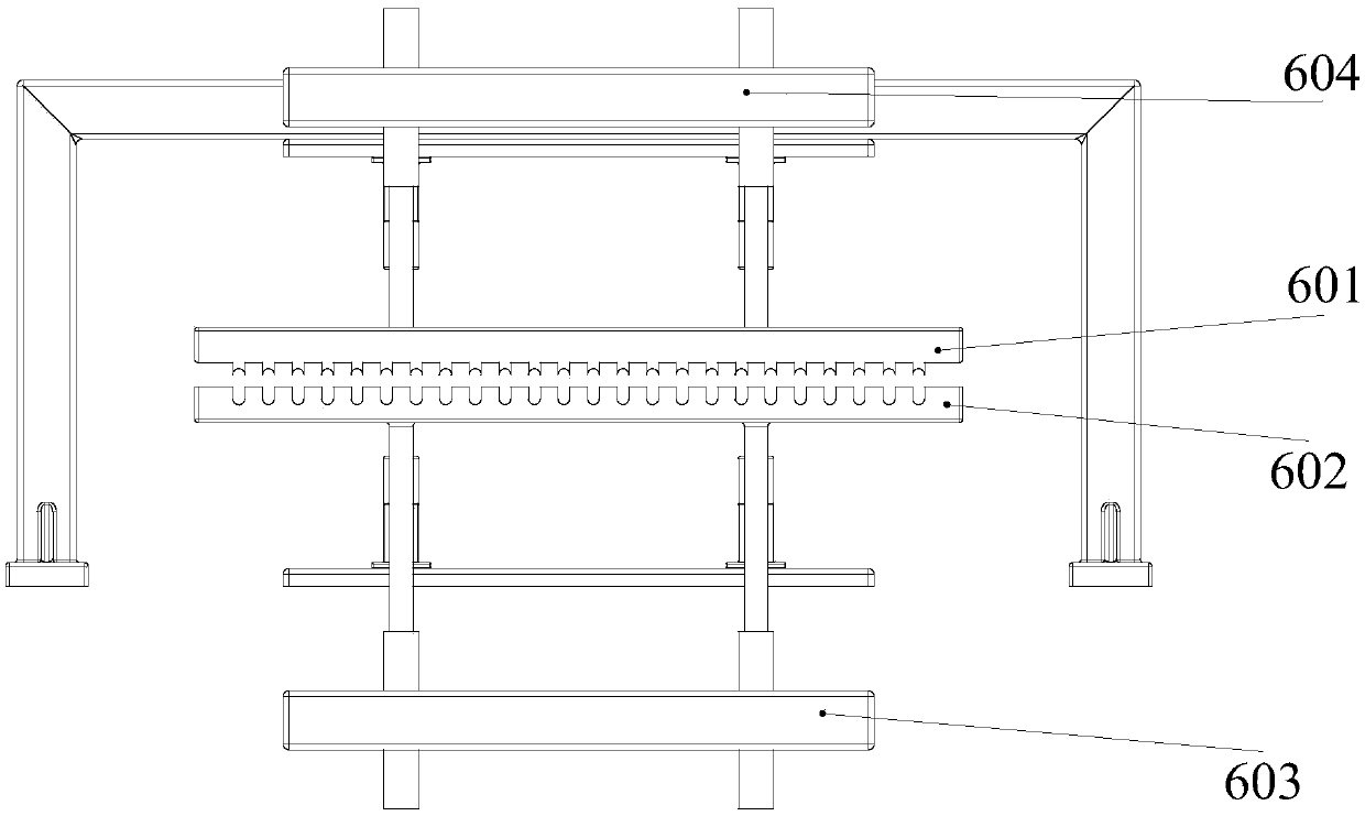
[0024] refer to figure 1 , figure 2 , Figure 5 , a row of U-shaped tubes has been placed between the tube placement groove 304 and the lower tooth plate 602 at the previous station. Next, the lead screw motor guide rail 4 drives the push tube assembly 3 to move for a certain distance in the direction of the heat exchanger 9 to be intubated. 302 presses against the U-shaped tube 5, and cooperates with the tube placement groove 304 to limit the vertical direction of the U-shaped tube 4. Then the guide rail 4 of the screw motor drives the pushing tube assembly 3 to move toward the heat exchanger 9 to be intubated, and the pushing tube plate 306 pushes the U-shaped tube 5 to inse...


PUM


Abstract

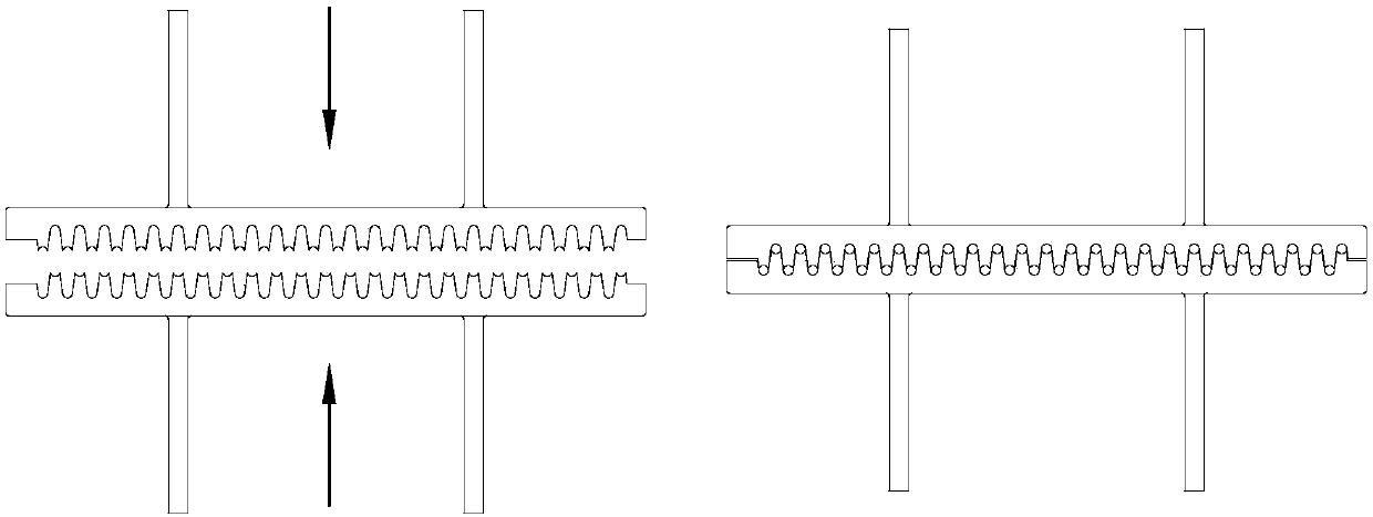
The invention designs a finned pipe type heat exchanger pipe inserting mechanism, which comprises a U-shaped pipe fixing assembly used for clamping and fixing a U-shaped pipe, a pipe pushing assemblyused for pushing the U-shaped pipe and a lead screw motor rail. Through the design of a tooth-shaped clamping mechanism, the clamping mechanism can more stably clamp the U-shaped heat dissipation pipe, and flat inserting and oblique inserting operation of the U-shaped heat dissipation pipe can be met at the same time. Meanwhile, the problem that in the prior art, the manual pipe inserting efficiency is low can be solved, and automatic operation of the pipe inserting procedure is achieved. The assembling effect of the heat exchanger can be greatly improved, and then the yield of the heat exchanger is increased.

Description

technical field [0001] The invention relates to the technical field of assembly machinery, in particular to a highly automated production device for inserting and inserting heat exchanger tubes in rows. Background technique [0002] The heat exchanger tube insertion platform is a highly automated device that can accurately and smoothly insert the cooling tube into the tube hole of the cooling fin. The structure of the heat exchanger mainly includes fins and heat pipes. Both the heat sink and the double-side splint are stamped and formed by a stamping die, and tube holes are formed on the formed splint and heat sink. In the prior art, it is necessary to manually form the required cooling fins and splints, and then manually insert the cooling tubes into the tube holes of the heat exchanger. [0003] Due to the large number of fins in the heat exchanger, each fin is relatively thin, and the diameter of the tubes that need to be intubated is small and there are many pipelines....

Claims


Application Information

Patent Timeline
Patent Type & Authority Applications(China)
IPC IPC(8): B23P19/02
CPCB23P19/02B23P2700/09
Inventor 张斌王晓辉高军巩守禄
Owner SHANDONG UNIV
Learn More