
Water-cooled water-driven cooling charging pile

A charging pile, water-driven technology, applied in electric vehicle charging technology, charging stations, electric vehicles, etc., can solve the problems of inability to adapt to heat dissipation conditions, heat can not be discharged in time, etc., to achieve safe use, easy to operate, not easy to leak water. Effect

Active Publication Date: 2020-04-03
CHANGZHOU INST OF DALIAN UNIV OF TECH
View PDF9 Cites 0 Cited by
  • Summary
  • Abstract
  • Description
  • Claims
  • Application Information

AI Technical Summary

Problems solved by technology

[0005] The purpose of the present invention is to provide a water-cooled water-driven cooling charging pile to solve the problem that the charging pile generates a lot of heat during the working process in the above background technology. Especially in summer, the heat cannot be discharged in time, and the conventional heat dissipation method cannot be adapted. The problem of heat dissipation in high temperature weather

Method used


Image

  • Water-cooled water-driven cooling charging pile
  • Water-cooled water-driven cooling charging pile
  • Water-cooled water-driven cooling charging pile

Examples


Embodiment 1

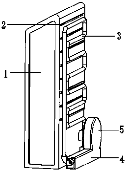
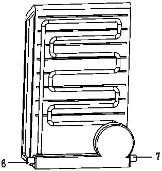
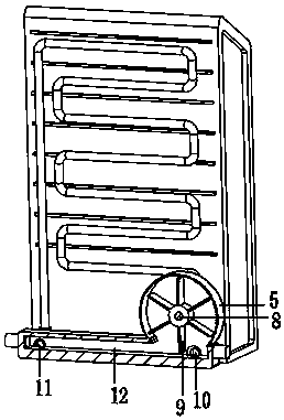
[0027] A specific application of this embodiment is: the present invention continuously pours water into the water channel 4, part of the water flow enters the water storage pipe 10, flows into the inner cavity of the water storage tank 17, and passes the water through the water channel 4, so that the water flow impacts the blades 9, The blade 9 can be rotated so that the impeller main shaft 8 can continue to rotate, the rotation of the impeller main shaft 8 drives the driving shaft 16 to rotate, and the meshing between the driving gear 19 and the driven gear 21 enables water to be sucked into the gap between the teeth. It is brought into the water pipe 3 from both sides of the pump water tank 14. Through the reduction of the gap between the teeth, the water is pumped out to realize the water intake, and the water flows through the water pipe 3, so that the flow of water in the water pipe 3 passes through the heat conduction effect of the heat conduction plate 2 , so that the h...

Embodiment 2

[0029] A specific application of this embodiment is: the present invention connects the water channels 4 of each group of charging piles 1 through an external water pipe, and by continuously pouring water into the water channel, part of the water flows into the water storage pipe 10 and flows into the inner cavity of the water storage tank 17. Through the water flowing through the water channel 4, the water flow impacts the blade 9, so that the blade 9 can rotate, so that the impeller main shaft 8 can continue to rotate, the rotation of the impeller main shaft 8 drives the driving shaft 16 to rotate, and the driving gear 19 and the driven gear The meshing of 21 enables water to be sucked into the gap between the teeth, and is brought into the water pipe 3 from both sides of the pump water tank 14. Through the reduction of the gap between the teeth, the water is pumped out to realize water intake, and the water flows through the water pipe 3, so that The flow of water in the wat...


PUM


Abstract

The invention discloses a water-cooled water-driven cooling charging pile in the technical field of charging pile heat dissipation. The water-cooled water-driven cooling charging pile includes a charging pile body; heat conduction plates are uniformly inserted into the outer wall of the rear end of the charging pile body; a hydrodynamic box and a water cooling device are arranged on the outer sideof the charging pile; the water-cooling device comprises a water pipe, a water pumping tank and a water storage tank; the water storage tank is communicated with the hydrodynamic tank; the water storage tank is communicated with the water pumping tank through a connecting pipe; a driving shaft and a driven shaft are inserted into an inner cavity of the pump water tank; a driving gear is fixedly mounted on the outer wall of the driving shaft; a driven gear is fixedly mounted on the outer wall of the driven shaft; the driving gear is meshed with the driven gear; the hydrodynamic box comprises an impeller box and a water passing groove, an impeller main shaft is transversely inserted into an inner cavity of the impeller box, the impeller main shaft is fixedly connected with the driving shaft, a plurality of sets of blades are fixedly installed on the outer wall of the impeller main shaft; the cooling effect of multiple sets of charging piles can be controlled at the same time, and the water-cooled water-driven cooling charging pile is suitable for outdoor charging piles exposed to the sun for a long time in high-temperature weather.

Description

technical field [0001] The invention relates to the technical field of heat dissipation of charging piles, in particular to a water-cooled water-driven cooling charging pile. Background technique [0002] An electric vehicle refers to a vehicle powered by a vehicle-mounted power supply, driven by a motor to drive the wheels, and conforming to the requirements of road traffic and safety regulations. Its composition includes: electric drive and control system, mechanical system such as driving force transmission, and working device to complete the predetermined task. Due to its smaller impact on the environment than traditional cars, its prospects are widely optimistic, but the current technology is still immature. With the development of electric vehicle technology, especially the country's continuous increase in air pollution control, electric vehicles, one of the best alternatives to traditional power vehicles, are developing rapidly. [0003] At present, charging piles g...

Claims


Application Information

Patent Timeline
IPC IPC(8): B60L53/31B60L53/302
CPCB60L53/302B60L53/31Y02T10/70Y02T10/7072Y02T90/12
Inventor 李强邹瑞洵
Owner CHANGZHOU INST OF DALIAN UNIV OF TECH
Learn More