
An electric locomotive and its traction circuit

A technology for electric locomotives and traction circuits, which is applied in the field of rail transit and can solve problems such as increased costs and reduced reliability of train circuits

Active Publication Date: 2021-02-05
ZHUZHOU ELECTRIC LOCOMOTIVE CO LTD
View PDF7 Cites 2 Cited by
  • Summary
  • Abstract
  • Description
  • Claims
  • Application Information

AI Technical Summary

Problems solved by technology

However, due to the need to add an additional chopper boost circuit, it will increase the cost and reduce the reliability of the train circuit

Method used


Image

  • An electric locomotive and its traction circuit
  • An electric locomotive and its traction circuit
  • An electric locomotive and its traction circuit

Examples


Embodiment Construction

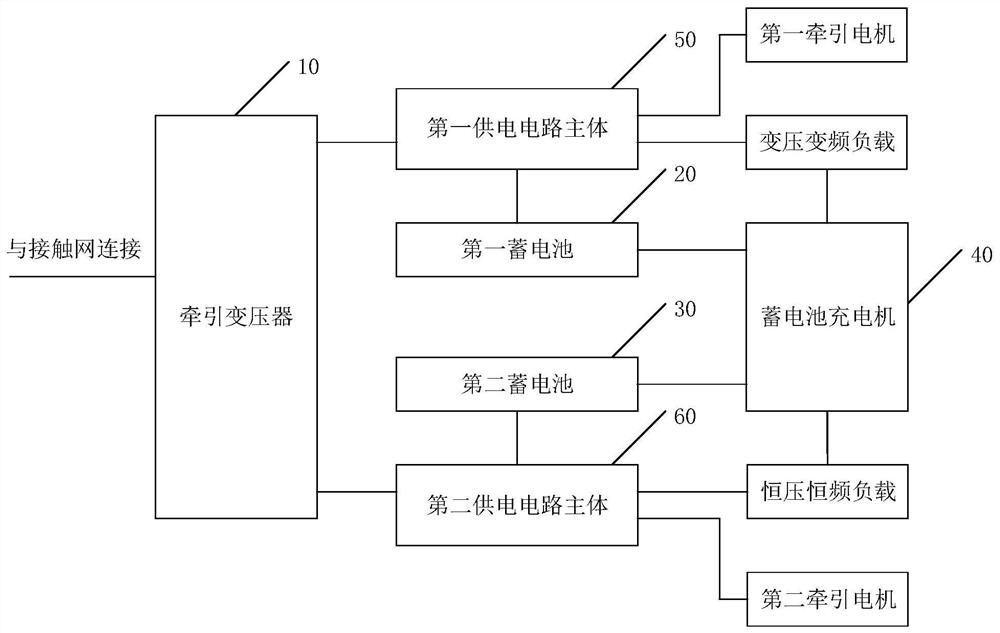
[0055] The core of the invention is to provide a traction circuit of an electric locomotive, which is beneficial to reduce the cost of the traction circuit of the electric locomotive and ensure the reliability of the circuit. In addition, it is also conducive to improving the utilization rate of energy conversion.

[0056] In order to enable those skilled in the art to better understand the solution of the present invention, the present invention will be further described in detail below in conjunction with the accompanying drawings and specific embodiments. Apparently, the described embodiments are only some of the embodiments of the present invention, but not all of them. Based on the embodiments of the present invention, all other embodiments obtained by persons of ordinary skill in the art without making creative efforts belong to the protection scope of the present invention.

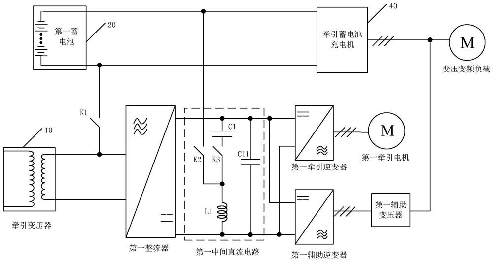
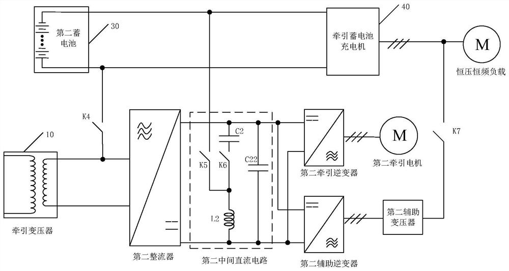
[0057] Please refer to figure 1 , figure 1 It is a structural schematic diagram of a tractio...


PUM


Abstract

The present application discloses a traction circuit of an electric locomotive, comprising: a traction transformer; a first battery and a second battery; a battery charger charges the first battery and the second battery in the charging mode; The output current is inverted to supply power for constant voltage and constant frequency loads; when the main body of the first power supply circuit is in the catenary power supply mode, it converts the electric energy of the catenary to supply power for the first traction motor and variable voltage and variable frequency load; when in the battery mode, it converts the first battery The electric energy of the second power supply circuit supplies power for the first traction motor and variable voltage and variable frequency load; when the main body of the second power supply circuit is in the catenary power supply mode, it converts the electric energy of the catenary to supply power for the second traction motor and constant voltage and constant frequency load; The electric energy of the second storage battery supplies power for the second traction motor. Applying the solution of the present application is beneficial to reduce the cost, ensure the reliability of the circuit, and improve the utilization rate of energy conversion. The application also discloses an electric locomotive, which has corresponding effects.

Description

technical field [0001] The invention relates to the technical field of rail transit, in particular to an electric locomotive and its traction circuit. Background technique [0002] The traditional electric locomotive has a single form of power supply and relies heavily on catenary power supply. When it is disconnected from the catenary or the catenary line fails, the locomotive will stop running because it cannot receive current. Therefore, electric locomotives with auxiliary power are used more and more. For example, various forms of electric locomotives with auxiliary power, such as internal combustion engine-battery, internal combustion engine-supercapacitor, internal combustion engine-fuel cell, fuel cell-battery, and catenary-battery, have appeared at present. [0003] At present, for high-power locomotives powered by AC catenary, the traction electric drive system generally adopts AC-DC-AC structure, and the voltage of the intermediate DC link is generally between 180...

Claims


Application Information

Patent Timeline
Patent Type & Authority Patents(China)
IPC IPC(8): B61C3/00B61C3/02H02M5/458H02P27/06
CPCB61C3/00B61C3/02H02M5/4585H02P27/06Y02T30/00
Inventor 索建国康明明邹焕青雷欣赵玉玲贾岩鑫
Owner ZHUZHOU ELECTRIC LOCOMOTIVE CO LTD
Learn More