Stress measurement method and stress measurement light path device

A technology of stress measurement and optical path, which is applied in the direction of measuring device, measuring force, and the measurement of the change force of the optical properties of the material when it is stressed, which can solve the problems of limited applicability, affecting the accuracy and error of calculation, etc. , to achieve the effect of convenient calculation and enhanced applicability

Inactive Publication Date: 2020-04-03
SOUTH CHINA UNIV OF TECH
View PDF4 Cites 4 Cited by
  • Summary
  • Abstract
  • Description
  • Claims
  • Application Information

AI Technical Summary

Problems solved by technology

However, analyzing the source of the experimental error, it can be found that although the experiment assumes that the loads on both sides are evenly distributed, which is reasonable, it is actually required that the boundary line between the speckle pattern and the photoelastic part made on the model before the experiment is perpendicular to the shape of the model The bisectors coincide, otherwise errors are likely to occur
[0007] The existing photoelastic and digital speckle mixed two-dimensional stress measurement method proposed by Li Bin and Yang Guobiao needs to find the middle dividing line on the surface of the sample. The dividing line is perpendicular to the optical axis of the photoelastic method, and the two sides of the dividing line are respectively Make photoelastic coatings and digital speckle coatings; or make samples with photoe

Method used


Image

  • Stress measurement method and stress measurement light path device
  • Stress measurement method and stress measurement light path device
  • Stress measurement method and stress measurement light path device

Examples


Embodiment 1

[0039] See attached figure 1 and image 3 , the stress measurement method that the present invention provides for the parallel photoelastic method of photoelastic material sample and digital image correlation method, it comprises the following steps:

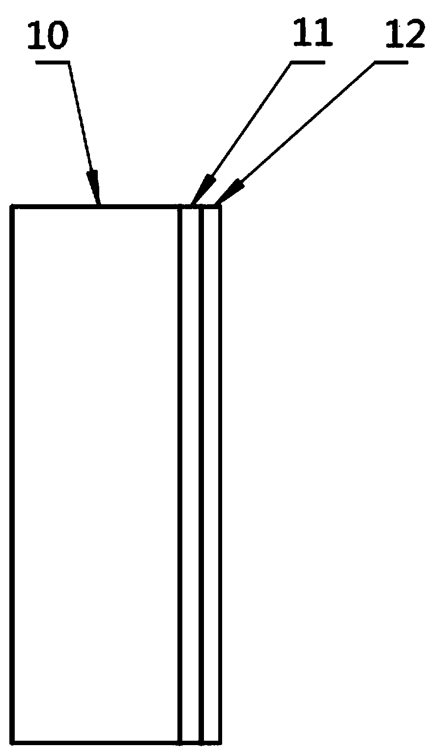
[0040] (1) A photoelastic material sample body 10 made of a single photoelastic material is set, and a coating structure is arranged on the outside of the sample body, and the coating structure includes a reflective coating 11 coated on one side of the sample body and is arranged on The speckle pattern 12 outside the reflective coating 11; the above-mentioned reflective coating 11 can reflect an image, and when stress measurement is performed, the reflective coating 11 will reflect the image after passing through the photoelastic sample, and perform a reflective photoelastic experiment The principal stress difference on one side can be obtained;

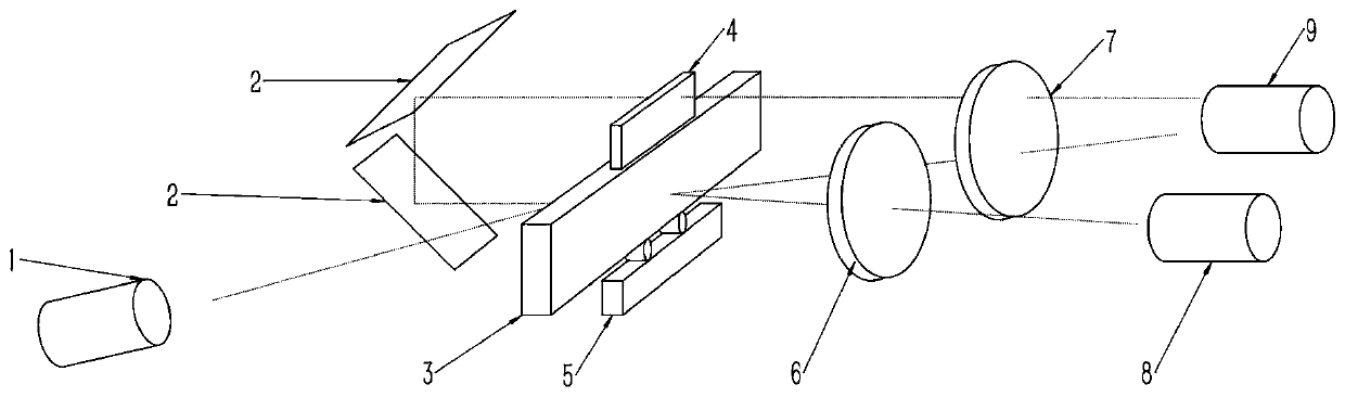
[0041] (2) A stress measurement optical path device is set, which includes a sam...

Embodiment 2

[0050] See attached figure 2 and attached image 3 , the stress measurement method that the present embodiment provides for the photoelastic method and the digital image correlation method parallel of the non-photoelastic material sample, it comprises the following steps:

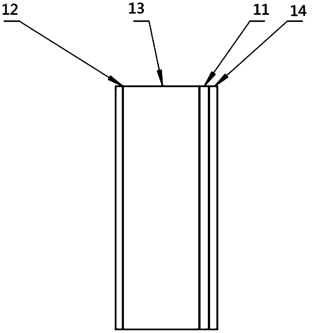
[0051] (1) Set a non-photoelastic material sample body 13 mainly made of metal or non-metallic materials, and one side surface of the non-photoelastic material sample body 13 is formed by grinding, painting or frosting, sandblasting process A speckle pattern, the other side of which is provided with a mirror surface or a plated reflective layer 11, and a photoelastic material layer 14 is also provided outside the mirror surface or reflective layer 11;

[0052] (2) A stress measurement optical path device is set, which includes a sample 3, a speckle method light source 1, a mirror 2, a supporting loading mechanism 5, a polarizer 6, an analyzer 7, a polarized light source 8 and an image acquisition unit 9, I...

Embodiment 3

[0061] See attached Figure 4 , what this embodiment provides is a stress measurement method and device in which the photoelastic method and the digital image correlation method in this embodiment are implemented on the basis of the above-mentioned embodiment 1 or embodiment 2. The difference is that:

[0062] The parallel stress measurement method of the photoelastic method and the digital image correlation method in the present embodiment also includes the following steps:

[0063] (21) An image acquisition unit 9 can be arranged on both sides of the sample 3 to collect photoelastic experiment pictures and speckle experiment pictures at the same time; the reflector in the stress measurement optical path device is removed, and the sample 3 is provided with An image acquisition unit 9 is also arranged on one side of the speckle method light source. When the speckle method light source is activated, the image acquisition unit 9 can be activated to obtain the required speckle im...


PUM


Abstract

The invention discloses a stress measurement method. The method comprises the following steps of (1) arranging a sample main body made of a single photoelastic material and a coating structure thereof; (2) arranging a stress measurement light path device; (3) starting a light source, through an arranged light path, refracting a speckle coating for multiple times and then enabling the light to coaxially enter an image acquisition unit with a reflection photoelastic pattern; (4) starting an image acquisition device, and obtaining a speckle image and a photoelastic image at the same moment at thetwo sides of the sample; and (5) jointly solving the related experiment results of a photoelastic experiment and a digital image to obtain a stress component of any pixel point of the image. The invention further discloses the stress measurement light path device for implementing the method. According to the present invention, a photoelastic method and a digital image correlation method are simultaneously carried out at the two sides of the sample to obtain the stress difference and the strain value of the whole field of the sample, so that the methods can be used for the sample with asymmetric loads, and the measurement applicability is greatly enhanced.

Description

technical field [0001] The invention relates to the technical field of stress measurement, in particular to a stress measurement method and a stress measurement optical path device in which a photoelastic method and a digital image correlation method are used in parallel. Background technique [0002] Photoelastic stress separation methods include numerical method, experimental method and hybrid method. Oblique shot method, strip method and stripe coating method and scribing method; hybrid method is mainly based on various methods of equal sum line method and photoelastic-infrared thermal imaging method and recently appeared photoelastic-digital image correlation method . The initial stress calculation value of the shear stress difference method starts from the free boundary, and the stress value of a point in the model is calculated numerically. If there is a large error between the initial value and the actual value, for example, if the model boundary is machined, there a...

Claims


Application Information

Patent Timeline
IPC IPC(8): G01L1/24
CPCG01L1/241
Inventor 何军
Owner SOUTH CHINA UNIV OF TECH
Why Eureka
Try Eureka