
Water-resistant and oil-proof packaged differential pressure sensor

A differential pressure sensor, oil-proof technology, applied in the pressure difference measurement between multiple valves, instruments, measuring devices, etc., can solve the problems of large differential pressure sensor size, inconvenient application, large product volume, etc. Compensation function, small size, and the effect of improving water and oil resistance

Inactive Publication Date: 2020-04-03
QST CORP
View PDF5 Cites 5 Cited by
  • Summary
  • Abstract
  • Description
  • Claims
  • Application Information

AI Technical Summary

Problems solved by technology

[0002] At present, in the first-level packaging market, the packaging structure of differential pressure sensors mostly adopts transistor outline packaging, the packaging process is complicated, and the product volume is large.
There is only one micro-electro-mechanical system (MEMS) sensing part in the existing package. If temperature compensation function is required, it is usually necessary to add an application specific integrated circuit chip (Application Specific Integrated Circuit, referred to as ASIC chip) to realize temperature compensation. Compensation, the existing packaging structure makes the size of the differential pressure sensor larger after adding the ASIC chip, causing inconvenience in application

Method used


Image

  • Water-resistant and oil-proof packaged differential pressure sensor
  • Water-resistant and oil-proof packaged differential pressure sensor
  • Water-resistant and oil-proof packaged differential pressure sensor

Examples


Embodiment Construction

[0040] The following will clearly and completely describe the technical solutions in the embodiments of the present invention with reference to the accompanying drawings in the embodiments of the present invention. Obviously, the described embodiments are only some, not all, embodiments of the present invention. Based on the embodiments of the present invention, all other embodiments obtained by persons of ordinary skill in the art without creative efforts fall within the protection scope of the present invention.

[0041] It should be noted that, in the case of no conflict, the embodiments of the present invention and the features in the embodiments can be combined with each other.

[0042] The present invention will be further described below in conjunction with the accompanying drawings and specific embodiments, but not as a limitation of the present invention.

[0043] The present invention comprises a water-proof and oil-proof packaged differential pressure sensor, compri...


PUM


Abstract

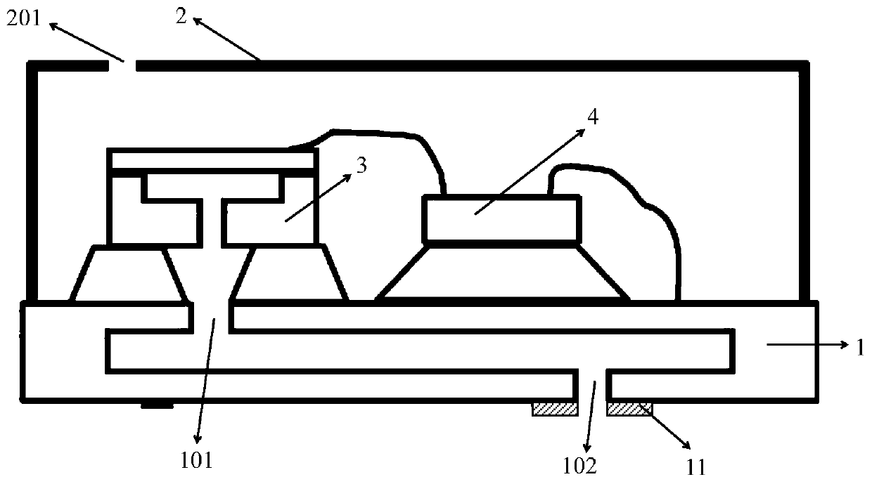
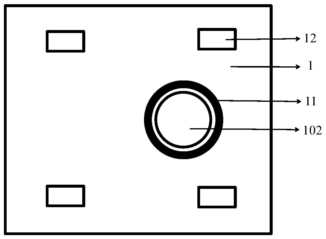
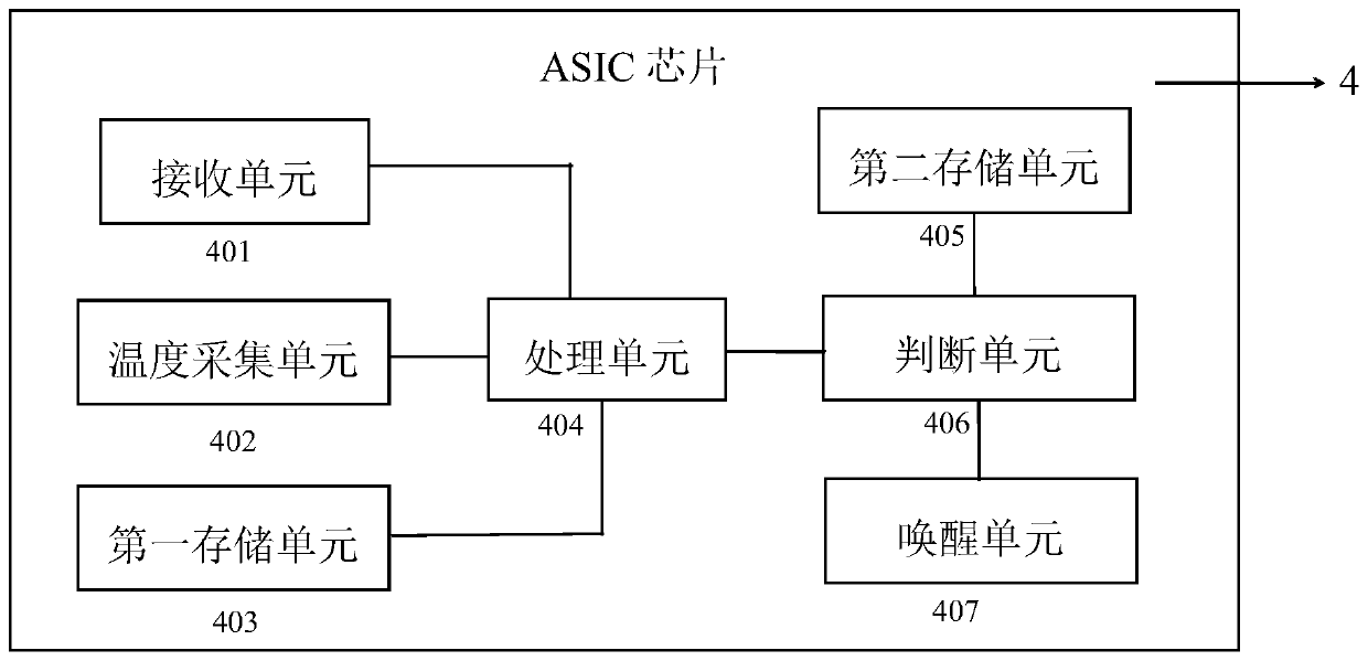
The invention relates to the technical field of micro electro mechanical systems, in particular to a water-resistant and oil-proof packaged differential pressure sensor, which comprises a substrate and a shell, and is characterized in that a sensing part and an integrated chip are arranged on the front surface of the substrate; the sensor comprises a cavity formed in the substrate; a first vent hole which is formed in the position, corresponding to the sensing part, of the front surface of the substrate and communicates with the cavity; a second vent hole which is formed in the back surface of the substrate and communicates with the cavity; a sensing part which detects ambient pressure, forms a first pressure signal and outputs the first pressure signal to the integrated chip; and an integrated chip which carries out temperature compensation on the first pressure signal according to a preset compensation coefficient so as to form a second pressure signal to be output. The sensor has the advantages that the temperature compensation function of the differential pressure sensor can be guaranteed, and the size of the differential pressure sensor is smaller; and meanwhile, under the condition that the working performance of an MEMS sensor is not influenced, the water resistance and oil resistance of the differential pressure sensor are improved.

Description

technical field [0001] The invention relates to the technical field of micro-electro-mechanical systems, in particular to a water- and oil-proof packaged differential pressure sensor. Background technique [0002] At present, in the first-level packaging market, the packaging structure of differential pressure sensors mostly adopts transistor outline packaging, the packaging process is complicated, and the product volume is large. There is only one micro-electro-mechanical system (MEMS) sensing part in the existing package. If temperature compensation function is required, it is usually necessary to add an application specific integrated circuit chip (Application Specific Integrated Circuit, referred to as ASIC chip) to realize temperature compensation. To compensate, the existing packaging structure increases the size of the differential pressure sensor after adding an ASIC chip, causing inconvenience in application. In addition, the demand for water and oil resistance of ...

Claims


Application Information

Patent Timeline
IPC IPC(8): G01L13/00G01L19/14G01L19/04
CPCG01L13/00G01L19/04G01L19/143
Inventor 谢国伟裘进陈清平林秋培朱伟琪夏颖
Owner QST CORP
Learn More