
Driving circuit of plurality of MOSFET switching tubes connected in parallel

A technology for driving circuits and switching tubes, which is used in electrical components, output power conversion devices, etc., can solve the problem of affecting the on-time and off-time of MOSFETs, it is difficult to quantify the increase of ceramic capacitors, and it is difficult to select ceramics with suitable capacitance values. Capacitance etc.

Inactive Publication Date: 2020-04-03
河南嘉晨智能控制股份有限公司
View PDF5 Cites 3 Cited by
  • Summary
  • Abstract
  • Description
  • Claims
  • Application Information

AI Technical Summary

Problems solved by technology

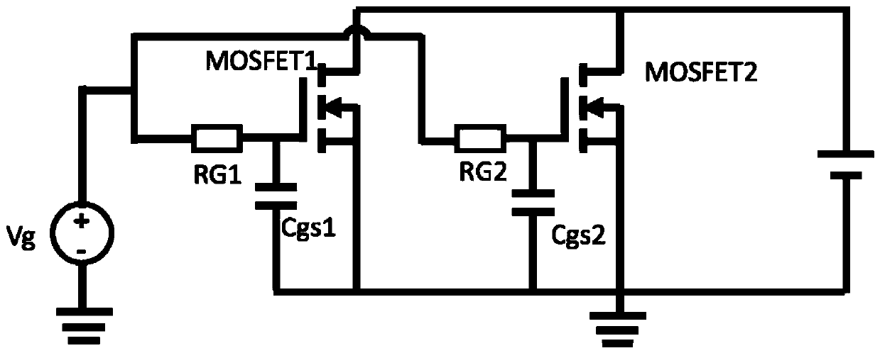
[0004] The disadvantage of the existing technology is that it is difficult to quantify the impact of increasing the capacitance value of ceramic capacitors and the corresponding MOSFET switching time, so it is not easy to select ceramic capacitors with appropriate capacitance values
At the same time, increasing the ceramic capacitor will also affect the turn-on time and turn-off time of the MOSFET

Method used


Image

  • Driving circuit of plurality of MOSFET switching tubes connected in parallel
  • Driving circuit of plurality of MOSFET switching tubes connected in parallel
  • Driving circuit of plurality of MOSFET switching tubes connected in parallel

Examples


Embodiment Construction

[0010] In order to make the technical problems, technical solutions and beneficial effects solved by the present invention clearer, the present invention will be further described in detail below in conjunction with the accompanying drawings. It should be understood that the specific embodiments described here are only used to explain the present invention, not to limit the present invention.

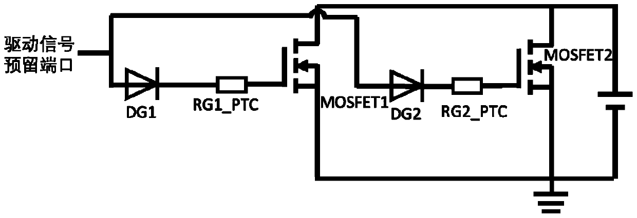
[0011] figure 2 A schematic diagram of a drive circuit for a plurality of parallel-connected MOSFET switches provided by an embodiment of the present invention. like figure 2 As shown, the drive circuit includes: MOSFET switch tubes MOSFET1 and MOSFET2 connected in parallel, PTC thermistors RG1_PTC and RG2_PTC, and switch diodes DG1 and DG2. The specifications and models of all MOSFET switch tubes are the same, the specifications and models of all PTC thermistors are the same, and the specifications and models of all switching diodes are the same. Among them, the diode DG1 and the ...


PUM


Abstract

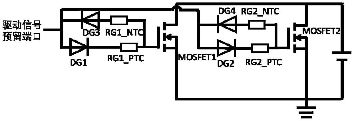
The invention discloses a driving circuit of a plurality of MOSFET switching tubes connected in parallel. The driving circuit is characterized in that any MOSFET switch tube connects a drive signal reserved port to a grid electrode of the MOSFET switch tube through a corresponding forward switch diode and a PTC thermistor, and connects the drive signal reserved port to the grid electrode of the MOSFET switch tube through a corresponding backward diode and an NTC thermistor. The PTC thermistor and the NTC thermistor are used for adjusting resistance values of the PTC thermistor and the NTC thermistor according to the temperature of the switch tube. In the switching-on process, if the temperature of a certain MOSFET switch tube is too high, the resistance value of the corresponding PTC thermistor is increased, and the switching-on speed of the PTC thermistor is decreased; when the circuit is turned off, if the temperature of a certain MOSFET is too high, the resistance value of the NTC thermistor corresponding to the MOSFET is reduced, and the turn-off speed is increased. According to the invention, the characteristics of the diode and the thermistor are utilized, so that the on / offtime difference between the parallel MOSFET switching tubes is reduced, and the phenomenon of non-uniform current between the parallel MOSFET switching tubes during on / off is reduced.

Description

technical field [0001] The invention provides a drive circuit for parallel MOSFET switching tubes, and relates to the field of drive circuit design for realizing power expansion in high-power low-voltage equipment such as switching power supplies and motor controllers. In particular, it relates to a driving circuit design scheme for a plurality of parallel-connected MOSFET switch tubes for realizing power expansion. Background technique [0002] In high-power low-voltage equipment such as switching power supplies and motor controllers, multiple MOSFET switches are usually connected in parallel to achieve power expansion. When a plurality of MOSFET switch tubes are connected in parallel to realize power expansion, the gate of each MOSFET switch tube is connected to a common drive signal reserved port through its own drive line. Due to the difference in the driving path lengths of the plurality of parallel MOSFET switch tubes, the inconsistencies in the complete turn-on or tu...

Claims


Application Information

Patent Timeline
Patent Type & Authority Applications(China)
IPC IPC(8): H02M1/088
CPCH02M1/088
Inventor 李飞姚欣
Owner 河南嘉晨智能控制股份有限公司
Learn More