
PLC control cabinet convenient for heat dissipation

A technology of control cabinets and heat dissipation holes, applied in the field of PLC control, can solve problems such as damage to electrical components, large capital investment, and short circuits, and achieve the effects of avoiding damage, reducing maintenance costs, and avoiding damage

Inactive Publication Date: 2020-04-03
西安安迈工业自动化技术有限公司
View PDF2 Cites 0 Cited by
  • Summary
  • Abstract
  • Description
  • Claims
  • Application Information

AI Technical Summary

Problems solved by technology

[0002] PLC control cabinet refers to programmable control cabinet, control cabinet refers to a complete set of control cabinets, electrical cabinets that can realize the control of motors and switches, PLC control cabinets, with overload, short circuit, phase loss protection and other protection functions, compact structure, stable work , Complete functions, can be combined according to the actual control scale, not only can realize single cabinet automatic control, but also can realize multiple cabinets to form a distributed control system through industrial Ethernet or industrial field bus network, PLC control cabinet can adapt to various sizes Industrial automation control occasions, widely used in electric power, metallurgy, chemical industry, papermaking, environmental protection, sewage treatment and other industries, according to a PLC control cabinet with the patent number CN201420511278. , the front of the cabinet, the box mouth, the horizontal support bar and the threading hole, thereby effectively facilitating the installation, operation, inspection and maintenance of the operator, and at the same time the wiring is neat and standardized; according to a PLC control cabinet with the patent number CN201820573903.2, the through hole The cabinet body, dust-proof sealing ring, partition, cooling hole, tripod, chute and slider are set up to effectively allow users to adjust the height of the partition according to different needs, thereby changing the space inside the cabinet. The size increases the practicability of the whole device. However, in the working environment of the existing PLC control cabinet, due to the large amount of heat generated by the electrical equipment or the influence of rain, the electrical components will be damaged, which will easily cause a short circuit or even a fire. lead to greater capital investment

Method used


Image

  • PLC control cabinet convenient for heat dissipation
  • PLC control cabinet convenient for heat dissipation
  • PLC control cabinet convenient for heat dissipation

Examples


Embodiment 1

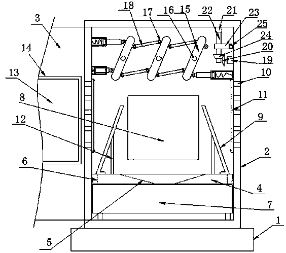
[0025] Such as Figure 1-4 As shown, the PLC control cabinet convenient for heat dissipation according to the embodiment of the present invention includes a base 1, a cabinet body 2 is provided on the top of the base 1, and a cabinet door 3 is movably connected to one side of the cabinet body 2. The inside of the body 2 is provided with a dividing plate 4, and the middle position of the dividing plate 4 is provided with a water guiding groove one 5 and a water guiding groove two 6 which are symmetrically arranged on both sides of the described water guiding groove one 5, and the bottom of the dividing plate 4 A sump 7 located at the inner bottom of the cabinet body 2 is provided, and electrical equipment 8 is provided on one side of the cabinet body 2, and water guides connected to the partition board 4 are symmetrically provided on both sides of the electrical equipment 8. plate 9, a plurality of cooling holes 10 are symmetrically provided on both sides of the cabinet body 2,...

Embodiment 2

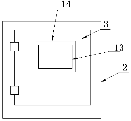
[0027] Such as figure 1 , 2 As shown, the cabinet door 3 is provided with an observation port 13, and the cabinet door 3 is provided with a glass window 14 on one side of the observation port 13. Obviously, the setting of the observation port 13 and the glass window 14 is convenient for work. Personnel do not need to open the cabinet body 2 when understanding the working conditions of the electrical equipment 8, and can observe the electrical equipment 8 conveniently.

[0028] Such as figure 1 As shown, the water guide plate 9 is an L-like structure, and the water guide plate 9 is arranged obliquely, and the bottom end of the water guide plate 9 is arranged on one side of the water guide groove 2 6. Obviously, the water guide plate 9 The inclined setting of the water plate 9 effectively guides the rainwater, thereby reducing the influence of the rainwater on the electrical equipment 8 .

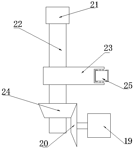
[0029] Such as figure 1 As shown, the middle position of one side of the water guidin...


PUM


Abstract

The invention discloses a PLC control cabinet convenient for heat dissipation. The control cabinet comprises a base; a cabinet is arranged at the top end of the base; one side of the cabinet body is movably connected with a cabinet door; a partition plate is arranged in the cabinet body; a first water guide groove and second water guide grooves symmetrically formed in the two sides of the first water guide groove are formed in the middle of the partition plate. A water collecting tank located at the bottom end in the cabinet body is arranged at the bottom end of the partition plate, electricalequipment is arranged on one side of the cabinet body, water guide plates connected with the partition plate are symmetrically arranged on the two sides of the electrical equipment, a plurality of heat dissipation holes are symmetrically formed in the two sides of the cabinet body, and dustproof nets located on one sides of the heat dissipation holes are arranged on the inner wall of the cabinetbody. The beneficial effects are that through the cooperation of the water guide plate, the first water guide groove and the second water guide groove, rainwater entering the cabinet body can be conveniently drained, the rainwater can conveniently enter the water collection groove to be collected, electrical equipment is prevented from being damaged due to damp, and the maintenance cost is effectively reduced.

Description

technical field [0001] The invention relates to the field of PLC control, in particular to a PLC control cabinet which is convenient for heat dissipation. Background technique [0002] PLC control cabinet refers to programmable control cabinet, control cabinet refers to a complete set of control cabinets, electrical cabinets that can realize the control of motors and switches, PLC control cabinets, with overload, short circuit, phase loss protection and other protection functions, compact structure, stable work , Complete functions, can be combined according to the actual control scale, not only can realize single cabinet automatic control, but also can realize multiple cabinets to form a distributed control system through industrial Ethernet or industrial field bus network, PLC control cabinet can adapt to various sizes Industrial automation control occasions, widely used in electric power, metallurgy, chemical industry, papermaking, environmental protection, sewage treatme...

Claims


Application Information

Patent Timeline
Patent Type & Authority Applications(China)
IPC IPC(8): H05K7/20H05K5/02H05K7/14
CPCH05K5/0217H05K7/1462H05K7/20136H05K7/20218H05K7/20272
Inventor 王文骏
Owner 西安安迈工业自动化技术有限公司
Learn More