Fundus camera fixation device and fundus camera

A camera and adjusting device technology, applied in fundus mirrors, eye testing equipment, medical science and other directions, can solve the problems of high assembly difficulty, high cost, large size of the lens barrel, etc., and achieve low assembly difficulty, low cost, and lens barrel. Small diameter effect

Pending Publication Date: 2020-04-07
SHANGHAI EAGLEVISION MEDICAL TECH CO LTD
View PDF0 Cites 2 Cited by
  • Summary
  • Abstract
  • Description
  • Claims
  • Application Information

AI Technical Summary

Problems solved by technology

[0004] Therefore, the technical problem to be solved by the present invention is to overcome the technical defects that the fundus camera in the prior art introduces the fixation lamp into the illumination light path, which leads to high equipment assembly difficulty, large lens barrel volume and high cost, thereby providing an Fundus camera fixation device with built-in fixation light

Method used


Image

  • Fundus camera fixation device and fundus camera
  • Fundus camera fixation device and fundus camera
  • Fundus camera fixation device and fundus camera

Examples


Embodiment 1

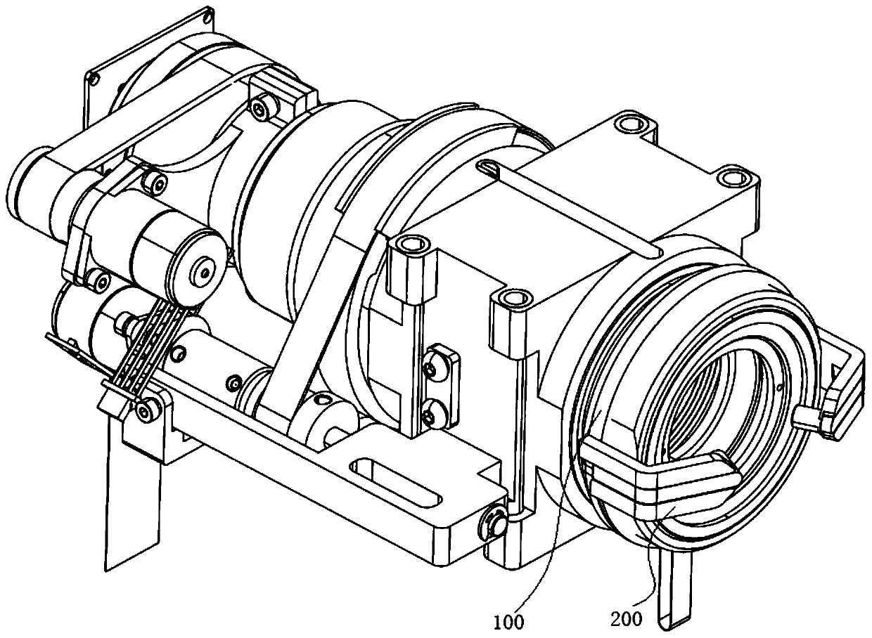
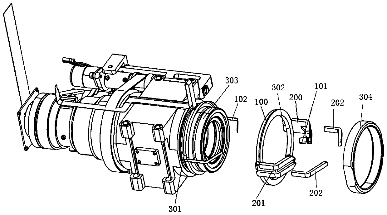
[0065] This embodiment provides a fundus camera fixation device, such as Figure 1-2 As shown, it includes: a ring-shaped fixing part 100, which is fixedly connected to the outside of one end of the front lens barrel 1 through a fixed structure; there are two mounting arms 200, one end is fixedly connected to the ring-shaped fixing part 100, and the other end extends to the One end of the front lens barrel 1 is opposite to each other, and has a mounting position 101 for mounting a fixation lamp.

[0066] The fixation device for the fundus camera of this embodiment installs the fixation lamp outside the lens barrel through the fixation device, which neither increases the difficulty of assembling the fundus camera nor increases the volume of the lens barrel, and increases the cost little.

[0067] The installation arm 200 is formed with a lead groove 201 for installing the lead wire 102 connected with the installation position 101 , and controlling the fixation lamp installed on...

Embodiment 2

[0070] This implementation provides a fundus camera, such as figure 1 As shown, it includes a front lens barrel 1, an eyepiece installed inside one end of the front lens barrel 1, and a fixation lamp, and the fixation lamp is installed on one end of the front lens barrel 1 through the fixation device in Embodiment 1. external.

[0071] Due to the adoption of the above-mentioned fixation device, the fundus camera of this embodiment is less difficult to assemble, has a small diameter of the lens barrel, and is low in cost.

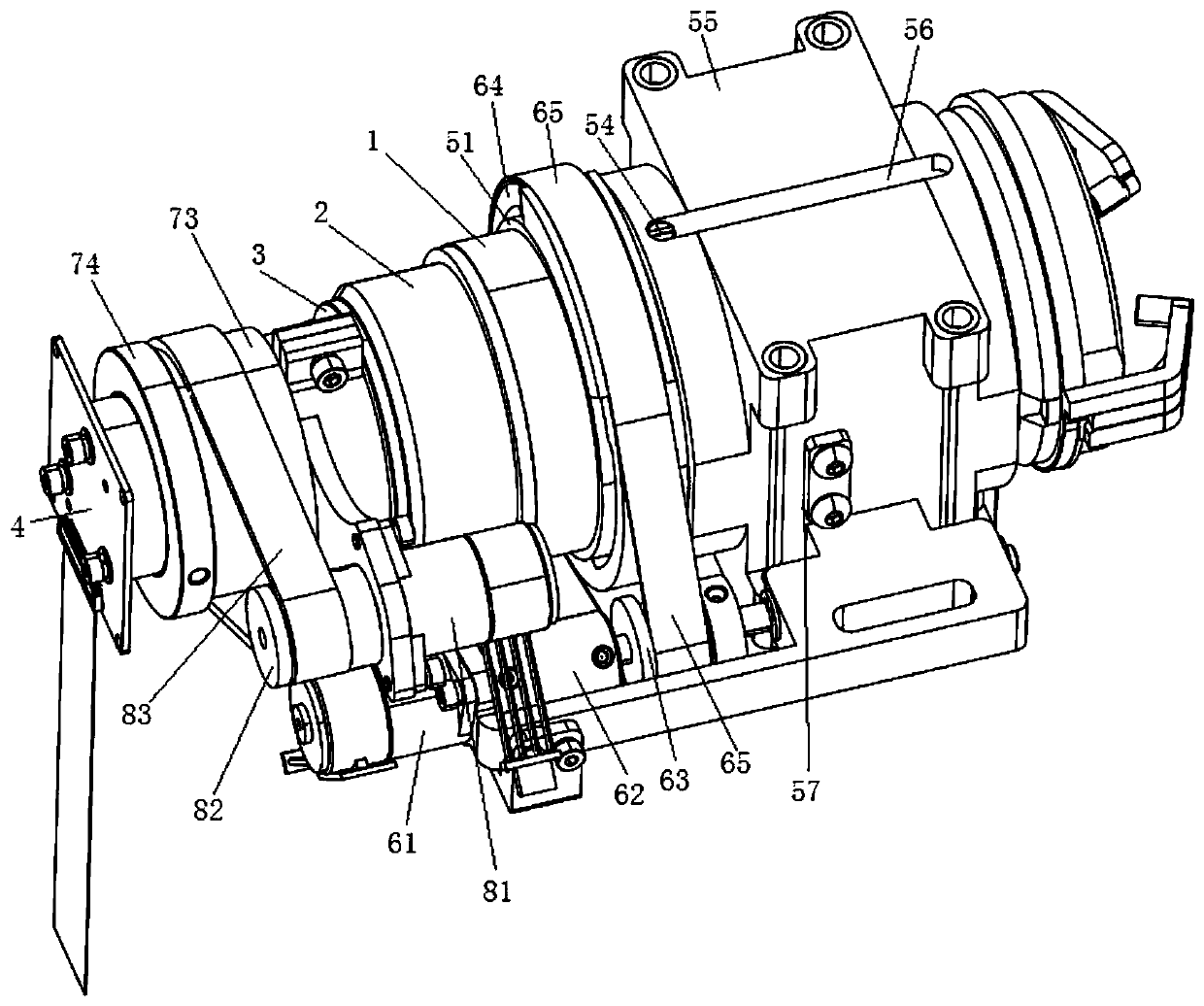
[0072] As an improvement, such as image 3 As shown, it also includes a rear lens barrel 2, one end of which is fixedly connected to the other end of the front lens barrel 1; The other end of the refraction adjustment rear cover 3 is suitable for fixedly installing the photographing assembly 4; it also includes a first adjustment device, which is used to adjust the front lens barrel 1 to do axial expansion, and drive the rear lens barrel 2 and the diopter ...


PUM


Abstract

The invention provides a fundus camera fixation device and a fundus camera. The fixation device comprises an annular fixing piece which is fixedly connected to the outer side of one end of a front lens cone through a fixation structure and at least one mounting arm. One end of the at least one mounting arm is fixedly connected with the annular fixing piece and the other end of the at least one mounting arm extends to be opposite to one end part of the front lens cone and is provided with a mounting position for mounting a fixation lamp. According to the fundus camera fixation device, a fixation lamp is installed outside the lens cone through the fixation device, so that the assembly difficulty of the fundus camera is not increased, the size of the lens cone is not increased, and the cost increase is small.

Description

technical field [0001] The invention relates to the technical field of medical ophthalmic optical instruments, in particular to a fundus camera fixation device and the fundus camera. Background technique [0002] The fundus camera is mainly used to take images of the retina of the human eye, so that medical personnel can check fundus diseases or assist medical personnel to judge the condition of other organs. The blood vessels of the fundus are the only blood vessels that can be directly observed through the body surface. Medical personnel can check whether there are lesions in the optic nerve, retina, choroid and refractive medium of the fundus through the fundus camera. Diagnosis and disease judgment, such as detecting cerebral infarction, cerebral hemorrhage, cerebral arteriosclerosis, brain tumor, diabetes, kidney disease, hypertension, retinopathy of prematurity, glaucoma, age-related macular degeneration, etc. by screening retinal photos. The earlier these diseases ar...

Claims


Application Information

Patent Timeline
IPC IPC(8): A61B3/14A61B3/12A61B3/00
CPCA61B3/0091A61B3/12A61B3/14
Inventor 任文斌常献刚和超张大磊
Owner SHANGHAI EAGLEVISION MEDICAL TECH CO LTD
Why Eureka
Try Eureka