Scrap iron removal device for wire cutting machine cooling liquid

A cleaning device, wire cutting machine technology, applied in attachments, electric processing equipment, metal processing equipment and other directions, can solve the problems of normal circulation of cooling liquid, iron filings doping, inconvenient cooling liquid recycling and other problems

Active Publication Date: 2020-04-07
共和精英塑胶五金制品(深圳)有限公司
View PDF11 Cites 4 Cited by
  • Summary
  • Abstract
  • Description
  • Claims
  • Application Information

AI Technical Summary

Problems solved by technology

During the machining process, the waste chips generated by the workpiece circulate with the coolant. When the waste chips in the coolant accumulate to a certain proportion, the waste chips will gather together and adhere to the cooling pipe of the machine tool, which is extremely It is easy to cause the blockage of the cooling pipe of the machine tool, and at the same time, iron filings are mixed in the cooling liquid, which is not convenient for the recycling and reuse of the cooling liquid. The method of removing waste chips from the cooling liquid in the prior art is to install a filter device in the 6th compartment of the cooling liquid tank network
[0004] The disadvantage of the above-mentioned prior art is that after a long period of time for one layer of filter screen, the iron filings may block one layer of filter screen. It is inconvenient to clean the iron filings on the filter

Method used


Image

  • Scrap iron removal device for wire cutting machine cooling liquid
  • Scrap iron removal device for wire cutting machine cooling liquid
  • Scrap iron removal device for wire cutting machine cooling liquid

Examples


Embodiment Construction

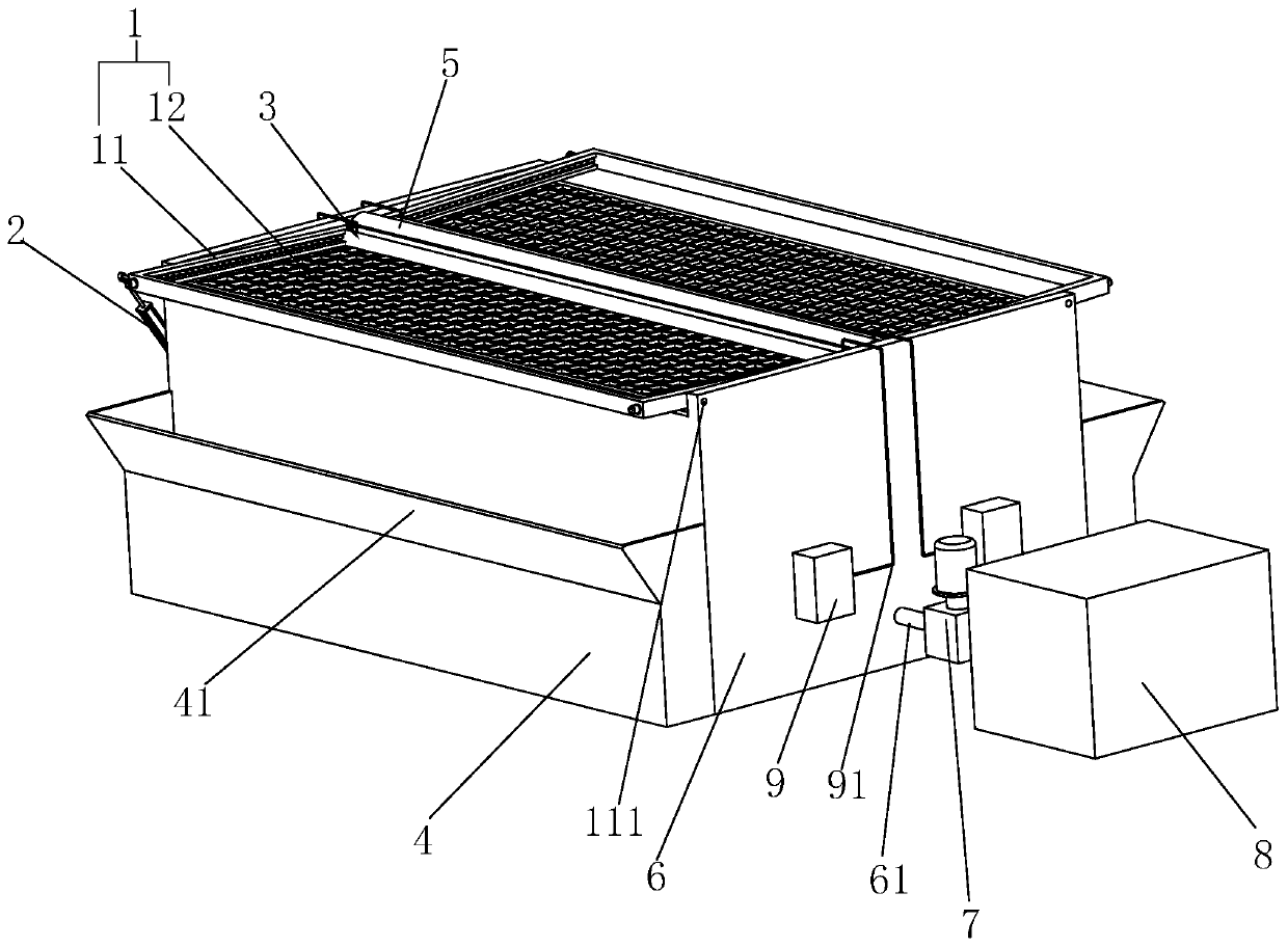
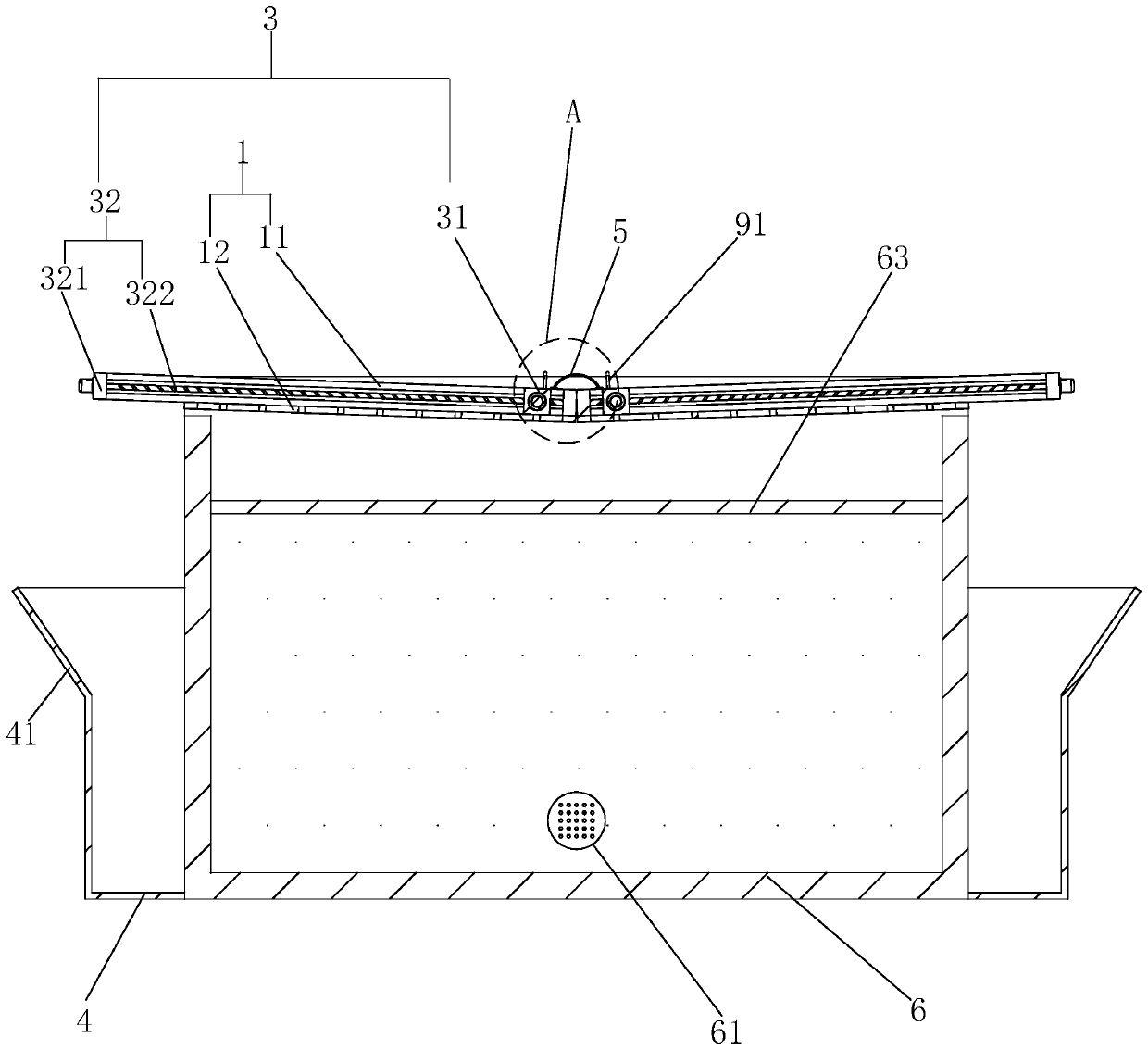
[0036] Such as figure 1As shown, the present invention introduces a chip cleaning device for wire cutting machine coolant, including a filter device 1, a driver, a cleaning device 3 and a collection box 4. The wire cutting machine includes a coolant tank 6 and a water adding mechanism 8, and the cooling The liquid tank 6 is connected with a water pump 7, and the water pump 7 is connected between the coolant tank 6 and the water adding mechanism 8, and then combined with figure 2 As shown, the upper surface of the coolant tank 6 is open, and the filter device 1 includes two overturn frames 11, which are symmetrically arranged on two opposite edges of the upper surface of the coolant tank 6, and the two overturn frames 11 are It is V-shaped and covers the upper surface of the coolant tank 6, and the V-shaped opening is upward, and two rotating rods 111 are respectively fixedly connected on the two opposite outer walls of the flip frame 11, and one of the two rotating rods 111 i...


PUM


Abstract

The invention discloses a scrap iron removal device for a wire cutting machine cooling liquid. The device comprises a filtering device, a driving part and a cleaning device, the filtering device comprises two overturning frames, the two overturning frames are symmetrically arranged on the two opposite edges of the upper surface of a cooling liquid box, the two overturning frames are V-shaped and shield the upper surface of the cooling liquid box, rotating rods are fixedly connected to two opposite outer side walls of the overturning frame respectively, the edge of one side of the cooling liquid box is rotationally connected to the rotating rod, one layer of a filter screen is fixedly arranged in the overturning frames, one layer of a filter screen is positioned between the rotating rod andthe edge, parallel to the rotating rod, of the overturning frame, the driving part is connected to the overturning frame and plays a role in supporting of the overturning frame, the driving part candrive the overturning frame to overturn relative to the cooling liquid box, a collecting box is fixedly connected to the outer side wall of the cooling liquid box, the collecting box is arranged belowthe overturning frame located on the outer side of the cooling liquid box, and the cleaning device can clean scrap iron on one layer of the filter screen. According to the device, the function of conveniently removing scrap iron in the cooling liquid is achieved.

Description

technical field [0001] The invention relates to the technical field of wire cutting machines, in particular to an iron chip cleaning device for cooling liquid of wire cutting machines. Background technique [0002] Injection molding is a method of producing industrial products. According to the injection molding raw materials, it can be divided into rubber injection molding and plastic injection molding. After the molding is completed, it needs to be further processed by a wire cutting machine. The commonly used wire cutting equipment is an electric spark cutting machine. [0003] The wire cutting machine in the prior art can refer to the invention patent with the authorized announcement number CN108817584B, including the body, the wire routing mechanism, the support column, the water adding mechanism, the fixing mechanism, the wire, the installation mechanism, the support plate, the adjustment mechanism, the limit mechanism and Cleaning mechanism, the metal wire rotates on...

Claims


Application Information

Patent Timeline
Patent Type & Authority Applications(China)
IPC IPC(8): B23H11/00B23H7/02
CPCB23H7/02B23H11/00
Inventor 颜招锋
Owner 共和精英塑胶五金制品(深圳)有限公司
Why Eureka
Try Eureka