
A steel structure truss welding process

A welding process and steel structure technology, applied in welding equipment, welding equipment, auxiliary welding equipment, etc., can solve the problems of high labor cost, steel position adjustment error, low work efficiency, etc., saving operation steps and avoiding the accumulation of errors , the effect of saving operation time

Active Publication Date: 2021-07-30
山东东恒新材料科技有限公司
View PDF8 Cites 0 Cited by
  • Summary
  • Abstract
  • Description
  • Claims
  • Application Information

AI Technical Summary

Problems solved by technology

[0004] (1) Due to the complex structure of the steel structure truss, the number of rebars and Z-shaped steel bars used is large. When welding, it often requires the cooperation of multiple workers. The work efficiency is low, the labor cost is high, and the temperature during welding is high. , it is easy to bring safety hazards to workers;
[0005] (2) When using manual methods to straighten and temporarily fix the steel in the welding process, it is necessary to adjust the position of each steel according to actual needs. The operation steps are cumbersome, and due to the inherent instability of manual operation, the position of the steel There are errors in the adjustment, and the accumulation of errors after multiple adjustments will affect the stability of the formed steel structure truss

Method used


Image

  • A steel structure truss welding process
  • A steel structure truss welding process
  • A steel structure truss welding process

Examples


Embodiment Construction

[0037] The embodiments of the present invention will be described in detail below with reference to the accompanying drawings, but the present invention can be implemented in many different ways defined and covered by the claims.

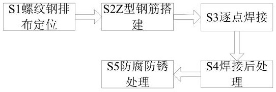
[0038] Such as Figure 1 to Figure 8As shown, a steel structure truss welding process mainly includes the following steps:

[0039] S1. Arrangement and positioning of the rebars: the staff puts the three rebars into the corresponding positions of the welding positioning fixture one by one, and locks the position of the rebars;

[0040] S2. Construction of Z-shaped steel bar: Lap the Z-shaped steel bar and rebar, and temporarily fix the position of the Z-shaped steel bar by welding positioning fixture;

[0041] S3. Point-by-point welding: use welding equipment to weld the Z-shaped steel bar and the rebar contact point by point to make a steel structure truss;

[0042] S4. Post-welding treatment: use sandpaper to grind the welded part, remove weldin...


PUM


Abstract

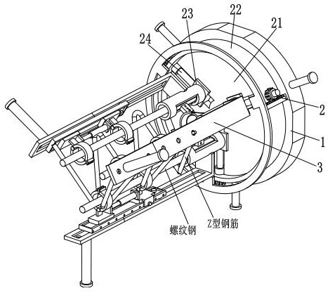
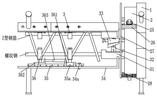
The invention relates to a steel structure truss welding process, which mainly includes the following steps: arrangement and positioning of threaded steel, construction of Z-shaped steel bars, point-by-point welding, post-welding treatment and anti-corrosion and anti-rust treatment. The welding positioning fixture used in the above steps includes a base, a positioning mechanism and a positioning mechanism. The positioning mechanism is installed on the left side of the base, and the side wall of the positioning mechanism is connected with the side wall of the positioning mechanism. The positioning mechanism includes a mounting Disc, working ring, sliding block, lead screw, rotating gear, transmission rack, connecting ring and telescopic rod, and positioning mechanism includes clamping cylinder, connecting plate, adjusting frame, supporting plate, sliding plate and positioning frame. The present invention adopts a mechanical method instead of several workers to fix the position of the steel, and simultaneously adjusts the positions of the three threaded steels through the position adjustment mechanism, which saves operation steps and avoids the accumulation of errors, and temporarily fixes the Z-shaped steel through the positioning mechanism , to ensure that the welding work is carried out stably.

Description

technical field [0001] The invention relates to the technical field of steel structure production, in particular to a steel structure truss welding process. Background technique [0002] Steel structure is a structure composed of steel materials, which is one of the main types of building structures. The components or components are usually connected by welds, bolts or rivets. Because of its light weight and easy construction, it is widely used in large factories, venues, super high-rises and other fields, and many trusses are mostly steel structures. [0003] In the process of manufacturing steel structure trusses, workers are required to weld rebar and Z-shaped steel bars, and there are many inconveniences in the welding process: [0004] (1) Due to the complex structure of the steel structure truss, the number of rebars and Z-shaped steel bars used is large. When welding, it often requires the cooperation of multiple workers. The work efficiency is low, the labor cost i...

Claims


Application Information

Patent Timeline
Patent Type & Authority Patents(China)
IPC IPC(8): B23K31/02B23K37/047
CPCB23K31/02B23K37/047
Inventor 潘岳燕熊芳
Owner 山东东恒新材料科技有限公司
Learn More