COS welding fixture for semiconductor laser

A technology of welding fixtures and lasers, applied in welding equipment, auxiliary welding equipment, welding/cutting auxiliary equipment, etc., can solve problems such as COS displacement deviation

Pending Publication Date: 2020-04-07
INST OF APPLIED ELECTRONICS CHINA ACAD OF ENG PHYSICS
View PDF0 Cites 6 Cited by
  • Summary
  • Abstract
  • Description
  • Claims
  • Application Information

AI Technical Summary

Problems solved by technology

[0003] The object of the present invention is to provide a COS welding jig for semiconductor lasers in view of the above disadvantages, and it is intended to solve the problems of COS displacement deviation caused by thermal expansion during COS welding.

Method used


Image

  • COS welding fixture for semiconductor laser
  • COS welding fixture for semiconductor laser
  • COS welding fixture for semiconductor laser

Examples


Embodiment 1

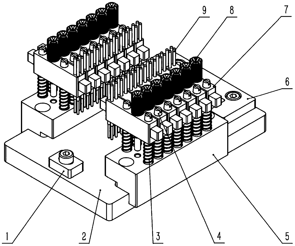
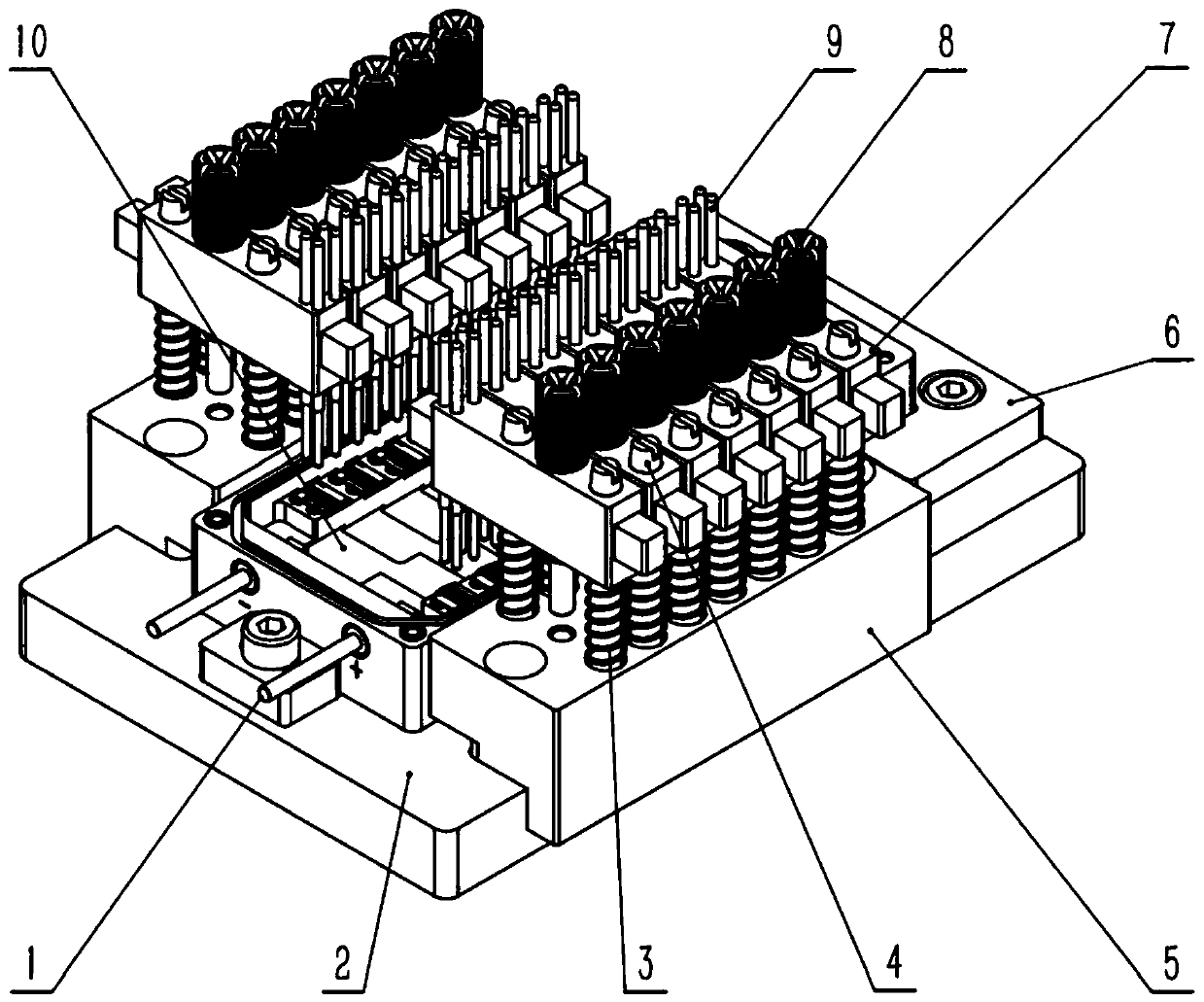
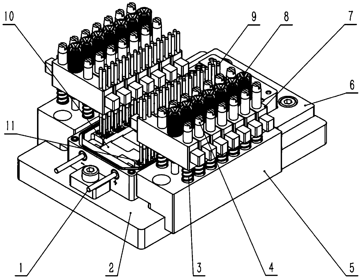
[0020] See attached Figure 1~3 . A COS welding fixture used in a semiconductor laser, comprising a bearing positioning assembly and at least one cantilever spring probe assembly; the bearing positioning assembly is used for bearing and positioning the shell base 10; the cantilever spring probe assembly includes at least one The positioning rod 4, the compression spring 3 corresponding to the positioning rod 4, at least one spring probe 9, the cantilever bracket 7 and the locking member; the positioning rod 4 is arranged on the bearing positioning assembly, and the positioning rod 4 is sheathed There is a compression spring 3; the compression spring 3 is compressed between the bearing positioning assembly and the cantilever bracket 7; the positioning rod 4 passes through the cantilever bracket 7; the locking member is used to limit the cantilever bracket 7 away from the bearing positioning assembly A certain distance position; the spring probe 9 is set on the cantilever suppor...

Embodiment 2

[0022] See attached Figure 1~3 . A COS welding fixture used in a semiconductor laser, comprising a bearing positioning assembly and at least one cantilever spring probe assembly; the bearing positioning assembly is used for bearing and positioning the shell base 10; the cantilever spring probe assembly includes at least one The positioning rod 4, the compression spring 3 corresponding to the positioning rod 4, at least one spring probe 9, the cantilever bracket 7 and the locking member; the positioning rod 4 is arranged on the bearing positioning assembly, and the positioning rod 4 is sheathed There is a compression spring 3; the compression spring 3 is compressed between the bearing positioning assembly and the cantilever bracket 7; the positioning rod 4 passes through the cantilever bracket 7; the locking member is used to limit the cantilever bracket 7 away from the bearing positioning assembly A certain distance position; the spring probe 9 is set on the cantilever suppor...

Embodiment 3

[0025] See attached Figure 1~3 . A COS welding fixture used in a semiconductor laser, comprising a bearing positioning assembly and at least one cantilever spring probe assembly; the bearing positioning assembly is used for bearing and positioning the shell base 10; the cantilever spring probe assembly includes at least one The positioning rod 4, the compression spring 3 corresponding to the positioning rod 4, at least one spring probe 9, the cantilever bracket 7 and the locking member; the positioning rod 4 is arranged on the bearing positioning assembly, and the positioning rod 4 is sheathed There is a compression spring 3; the compression spring 3 is compressed between the bearing positioning assembly and the cantilever bracket 7; the positioning rod 4 passes through the cantilever bracket 7; the locking member is used to limit the cantilever bracket 7 away from the bearing positioning assembly A certain distance position; the spring probe 9 is set on the cantilever suppor...


PUM


Abstract

The invention discloses a COS welding fixture for a semiconductor laser, and belongs to the technical field of COS welding. The COS welding fixture comprises a bearing and positioning assembly and atleast one cantilever spring probe assembly; the bearing and positioning assembly is used for bearing and positioning a tube shell base; the cantilever spring probe assembly comprises at least one positioning rod, pressure springs in one-to-one correspondence with the positioning rods, at least one spring probe, a cantilever support and a locking piece; the positioning rod is arranged on the bearing and positioning assembly, and is sleeved with the pressure spring; the pressure spring is compressed between the bearing and positioning assembly and the cantilever support; the positioning rod passes through the cantilever support; the locking piece is used for limiting the cantilever support at a position with a certain distance from the bearing and positioning assembly; the spring probe is arranged on the cantilever support and used for pressing the COS on the welding flux arranged on the tube shell base. The COS welding fixture for the semiconductor laser can effectively prevent COS fromgenerating displacement deviation in the welding process and improve COS positioning accuracy.

Description

Technical field [0001] The invention belongs to the technical field of COS welding, and specifically relates to a COS welding fixture used in a semiconductor laser. Background technique [0002] When welding the COS (Chip-On-Submount) in the semiconductor laser, it is necessary to quickly and accurately position the COS on the base of the case and fix it effectively to prevent the COS from deforming and shifting during the welding process Deviation, in order to realize the effective welding of COS on the shell base. The current existing welding clamps are relatively large in size, cannot be adjusted at a single point, and have low welding efficiency. In addition, due to thermal expansion when welding the COS, it is easy to cause displacement deviation of the COS, which ultimately leads to inaccurate positioning of the COS. Summary of the invention [0003] The purpose of the present invention is to provide a COS welding jig for semiconductor lasers in view of the above-mentioned ...

Claims


Application Information

Patent Timeline
Patent Type & Authority Applications(China)
IPC IPC(8): B23K37/04
CPCB23K37/0443
Inventor 张永刚雷军吕文强谢鹏飞王昭曹礼强高松信唐淳
Owner INST OF APPLIED ELECTRONICS CHINA ACAD OF ENG PHYSICS
Why Eureka
Try Eureka