Hydraulic and battery integrated vehicle composite energy system and control method thereof

A composite energy, electro-hydraulic control technology, applied in electric braking systems, electric vehicles, control drives, etc., can solve the problems of limited improvement of vehicle energy-saving effect, low braking energy recovery ratio, and low energy recovery efficiency, etc. To achieve the effect of improving vehicle economy, excellent power, and improving drivability

Active Publication Date: 2020-04-07
XIANGTAN UNIV
View PDF5 Cites 6 Cited by
  • Summary
  • Abstract
  • Description
  • Claims
  • Application Information

AI Technical Summary

Problems solved by technology

[0003] However, in the existing electric vehicle energy storage system, the braking energy recovery efficiency is double restricted by the motor speed and the battery SOC state, resulting in low energy recovery efficiency
On the one hand, the drive motor has a power generation speed threshold. When the motor speed is lower than a certain threshold during braking, the back electromotive force (induced electromotive force) of the motor is too low, and its own energy consumption will be greater than the recovered energy, so it is necessary to exit the power generation mode. The kinetic energy of the vehicle can only be consumed by mechanical friction braking
On the other hand, when the battery SOC is in a high value range, if the battery is charged further, the resulting battery overcharge will lead to reduced battery life or damage. When the SOC is higher than this limit, braking energy recovery is prohibited
The above restrictions lead to a low braking energy recovery ratio of electric vehicles under cyclic working conditions, and the energy-saving effect of the whole vehicle is limited.

Method used


Image

  • Hydraulic and battery integrated vehicle composite energy system and control method thereof
  • Hydraulic and battery integrated vehicle composite energy system and control method thereof
  • Hydraulic and battery integrated vehicle composite energy system and control method thereof

Examples


Embodiment Construction

[0031] The present invention will be further described below in conjunction with the accompanying drawings.

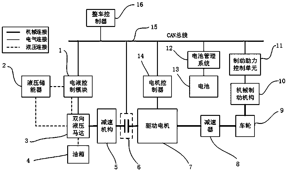
[0032] The vehicle composite energy system integrating hydraulic power and battery of the present invention includes a hydraulic accumulator 2, an electro-hydraulic control module 1, a bidirectional hydraulic motor 3, a speed reduction mechanism 5, a clutch 6, a drive motor 7, a battery 13, and a motor controller 14 And battery management system 12, brake booster control unit 11, CAN bus 15, vehicle controller 16;

[0033] The output shaft of the bidirectional hydraulic motor 3 is connected to one end of the rotor of the drive motor 7 through the reduction mechanism 5 and the clutch 6 , and the other end of the rotor of the drive motor 7 is connected to the wheel 9 through the reducer 8 . The two oil inlets of the bidirectional hydraulic motor 3 are respectively connected to the oil tank 4 and the hydraulic accumulator 2, the oil inlet of the hydraulic accumulator 2 is...


PUM


Abstract

The invention provides a hydraulic and battery integrated vehicle composite energy system and a control method thereof. The system comprises a vehicle control unit, a hydraulic accumulator, an electro-hydraulic control module, a bidirectional hydraulic motor, a speed reducing mechanism, a clutch, a driving motor, a speed reducer, a battery, a motor controller, a battery management system, a brakeboosting control unit and a CAN bus. An output shaft of the bidirectional hydraulic motor is connected with one end of a rotor of a driving motor through a reducing mechanism and a clutch; the other end of the rotor of the driving motor is connected with wheels through a reducer; a control port of the bidirectional hydraulic motor is electrically connected with the electro-hydraulic control module, and the bidirectional hydraulic motor, the electro-hydraulic control module, the clutch, the battery management system and the brake boosting control unit are connected to the CAN bus in parallel. Braking energy recovery can be implemented under the working conditions that the SOC value of the battery is higher than the highest charging threshold and the rotating speed of the driving system is lower than the lowest generating threshold rotating speed of the motor, the working condition range of braking energy recovery is expanded, and the braking energy recovery ratio is increased.

Description

technical field [0001] The invention belongs to the technical field of new energy vehicles, and in particular relates to a vehicle composite energy system integrating hydraulic power and batteries and a control method thereof. Background technique [0002] The rapid development of pure electric vehicle technology has become the development direction of traditional vehicles. The main contribution of pure electric vehicles to energy saving compared with traditional fuel vehicles is that the braking energy can be recovered through the motor, and the energy saving effect of electric vehicles depends to a large extent on the braking energy recovery efficiency of the vehicle under cycle conditions. Existing pure electric vehicles use batteries as energy storage devices. When the driver brakes, the vehicle control system controls the drive motor to switch to the power generation mode to provide braking torque to achieve braking energy recovery. [0003] However, in the existing el...

Claims


Application Information

Patent Timeline
Patent Type & Authority Applications(China)
IPC IPC(8): B60L7/10B60L15/20
CPCB60L7/10B60L15/20B60L15/2009B60L15/2054Y02T10/72
Inventor 傅兵朱泰平孟步敏刘金刚王伟达胡余良刘杰
Owner XIANGTAN UNIV
Why Eureka
Try Eureka