Vibrating blind sidewalk guide brick

A guiding brick and vibrating technology, applied in the field of vibrating blind road guiding bricks, can solve the problems of insignificant guiding effect and poor comfort, and achieve the effects of preventing deviation, reducing soreness and improving practicability.

Active Publication Date: 2020-04-07
陕西正光建设工程有限公司
View PDF5 Cites 7 Cited by
  • Summary
  • Abstract
  • Description
  • Claims
  • Application Information

AI Technical Summary

Problems solved by technology

[0004] The purpose of the present invention is to solve the disadvantages of poor comfort and inconspicuous guiding effect when the blind walk on the blind road guide bricks existing in the prior art, and propose a vibrating blind road guide brick

Method used


Image

  • Vibrating blind sidewalk guide brick
  • Vibrating blind sidewalk guide brick
  • Vibrating blind sidewalk guide brick

Examples


Embodiment 1

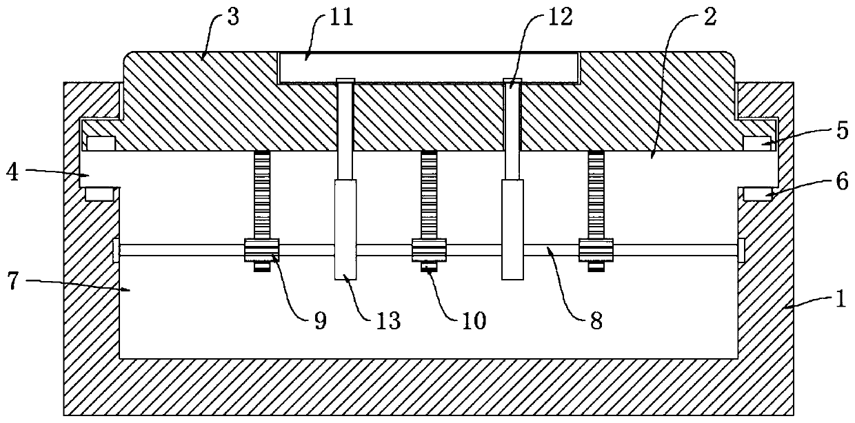
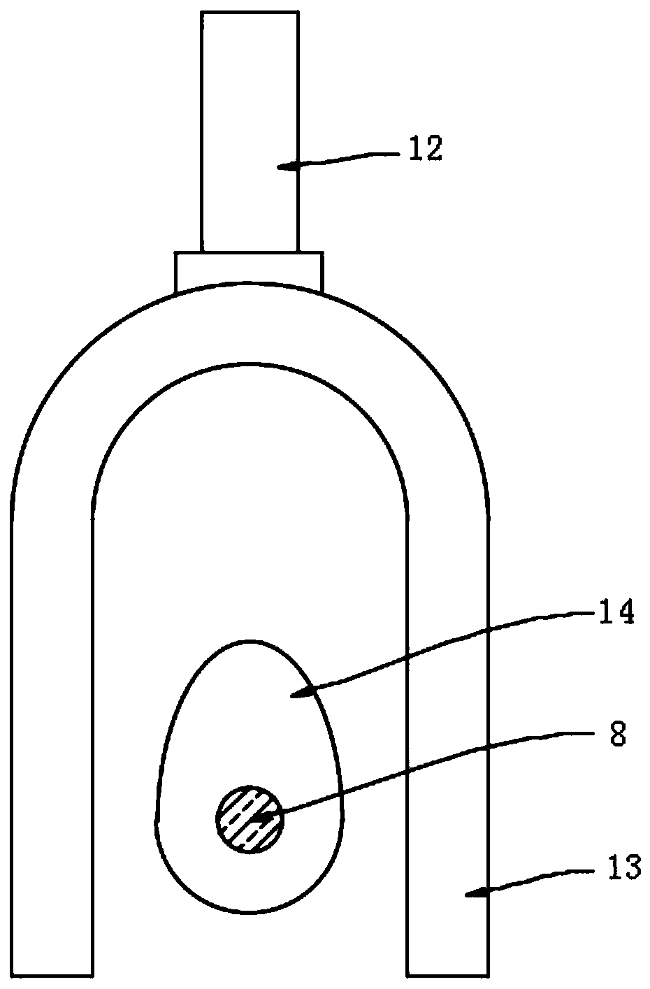
[0022] refer to Figure 1-3 , a vibrating blind road guide brick, comprising a brick body 1, a plurality of chutes 2 are evenly opened horizontally and in parallel on the brick body 1, each chute 2 is slidably connected with a guide bar 3, and the side walls of each chute 2 Limiting grooves 4 are provided on the tops, and the edge of each guide bar 3 extends into the corresponding limiting groove 4 . The lower end of each guide bar 3 is embedded with a first magnetic ring 5 , and the bottom side of each limiting groove 4 The walls are embedded with a second magnetic ring 6, and the first magnetic ring 5 and the corresponding second magnetic ring 6 have the same magnetic pole on the opposite side, then the guide bar 3 is under the repulsive force of the first magnetic ring 5 and the second magnetic ring 6. Its side wall is in contact with the upper groove wall of the limit groove 4, and the height difference between the upper end face of the guide bar 3 and the horizontal plane...

Embodiment 2

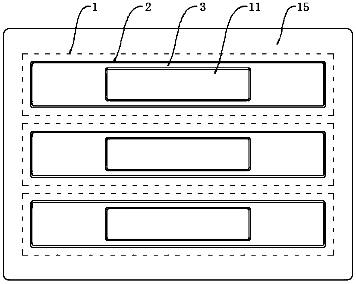
[0027] refer to Figure 4 , the difference between this embodiment and Embodiment 1 is: the upper end face of the brick body 1 is embedded with a ring light strip 15, and the ring light strip 15 can be made of LED lamp beads, and the LED lamp beads only need a small current. It can be lit, two micro-generators 16 are symmetrically arranged on the wall of the installation slot 7, the micro-generators 16 are alternating current generators, and the input shafts of the two micro-generators 16 are welded to the two ends of the rotating rod 8 respectively. , the output ends of the two micro-generators 16 are electrically connected to the ring light strip 15 through wires.

[0028] In this embodiment, when the gear 9 drives the rotating rod 8 to rotate, and the rotating rod 8 drives the input shaft of the micro-generator 16 to rotate, the micro-generator 16 generates alternating current and transmits it to the ring light strip 15 through the wire, then the ring light strip 15 is lit...


PUM


Abstract

The invention discloses a vibrating blind sidewalk guide brick. The brick comprises a brick body, a plurality of sliding grooves are evenly formed in the brick body. A guide strip is connected into each sliding groove in a sliding manner; a limiting groove is formed in the side wall of each sliding groove, the edge of each guide strip extends into the corresponding limiting groove, a first magnetic ring is embedded in the lower end of each guide strip, a second magnetic ring is embedded in the bottom side wall of each limiting groove, and the magnetic poles of the opposite sides of the first magnetic rings and the corresponding second magnetic rings are the same. By arranging the movable guide strips, the comfort level of the blind sidewalk can be improved; meanwhile, the tuning fork continuously vibrates and transmits the vibration to a vibration block by utilizing the movement of the guide strips, so that the blind can be quickly positioned and are prevented from deviating from the blind sidewalk, in addition, an annular lamp strip is lightened by utilizing the movement power generation of the guide strips at night, the effect of warning pedestrians can be achieved, and the practicability of the blind sidewalk is improved.

Description

technical field [0001] The invention relates to the technical field of municipal construction, in particular to a vibrating blind road guide brick. Background technique [0002] The blind road is a road facility specially designed to help the blind to walk. The guide is a kind of brick with straight protrusions, which is used to pave a straight blind path. The bulge creates a feeling of the stick and the sole of the foot, which helps guide the visually impaired to walk safely and in a straight line. [0003] However, the protrusions on the surface of the traditional blind road tiles are generally hard. When the blind walks on the blind road for a long time, it is easy to cause sore muscles on the soles of the feet, which brings pain to the blind and is inconvenient for the blind to walk. The tactile sensitivity decreases, which makes it easy for the blind to deviate from the blind road, causing accidents and dangers. In addition, due to the different physiques of people, bl...

Claims


Application Information

Patent Timeline
Patent Type & Authority Applications(China)
IPC IPC(8): E01C15/00E01C11/00E01C17/00E01F9/529F03G7/00
CPCE01C11/00E01C15/00E01C17/00E01F9/529F03G7/00
Inventor 秦文斌
Owner 陕西正光建设工程有限公司
Why Eureka
Try Eureka