Anti-abrasion circulating fluidized bed boiler

A circulating fluidized bed and anti-wear technology, which is applied to fluidized bed combustion equipment, fuel burned in a molten state, lighting and heating equipment, etc., can solve the problem of reduced gas and solid flow area and increased wear of both side wall tubes , easy to form eddy currents and other problems, to achieve the effect of reducing speed and concentration, simple and convenient maintenance, and high operating reliability

Active Publication Date: 2016-12-14
GUANGXI NANYIZAI SCI & TECH CO LTD
View PDF6 Cites 4 Cited by
  • Summary
  • Abstract
  • Description
  • Claims
  • Application Information

AI Technical Summary

Problems solved by technology

[0005] 2. The wear of the four corners of the furnace wall: this is caused by the relatively high concentration of the material flow in the four corners of the furnace
[0006] 3. Wear of the water-cooled wall tubes on both sides of the furnace outlet: the wear of the heating surface of the furnace roof is mainly due to the change of the flow direction of the gas and solid flows when they leave the furnace and enter the turning flue, and the flow area of ​​the gas and solid flows is reduced, resulting in the two Increased wear on sidewall tubes
This is mainly because the adherent flow in the irregular part is changed, and it is easy to form eddy current, which leads to the occurrence of wear

Method used


Image

  • Anti-abrasion circulating fluidized bed boiler
  • Anti-abrasion circulating fluidized bed boiler
  • Anti-abrasion circulating fluidized bed boiler

Examples


Embodiment

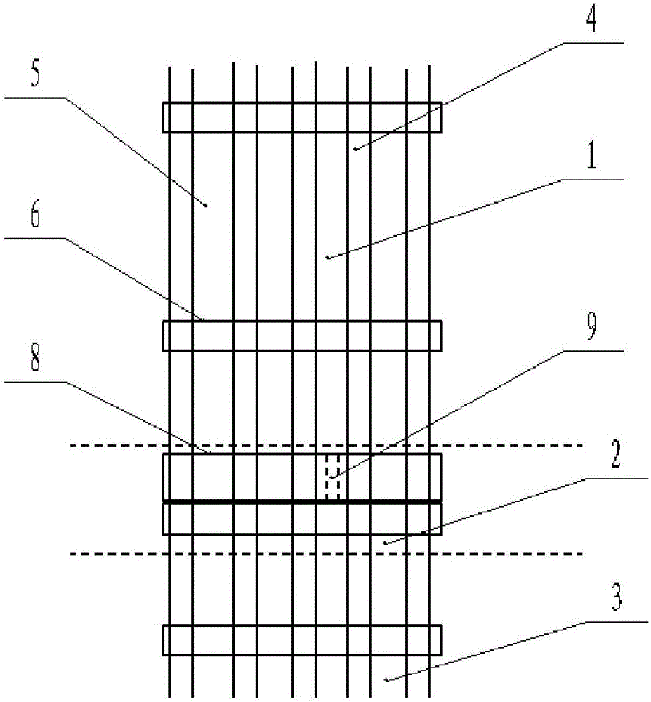
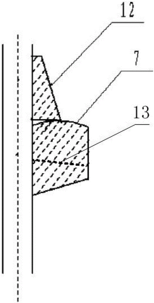
[0032] An anti-wear circulating fluidized bed boiler boiler, comprising a water wall, a dense phase zone 1, a transition zone 2 and a dilute phase zone 3, such as figure 1 and figure 2 As shown, the water cooling wall is formed by connecting the water cooling wall tube 4 and the fins 5, the surface of the water cooling wall is sprayed with a wear-resistant coating with a thickness of 2-5mm, and the water cooling wall is provided with a "V" shaped grip The nail 13 and the anti-wear beam 6 with a semi-trapezoidal cross-section, the grab nail 13 is welded on the fin, the anti-wear beam 6 is laid on the grab nail 13 and covers the grab nail 13, and the height of the laid anti-wear beam 6 is 140- 160mm, width 80-100mm. The anti-wear beam 6 is close to the nail 13 and the water-cooled wall pipe 4, and the anti-wear beam 6 also has a guide slope 7 for changing the direction of the particles.

[0033] At the same time, in order to further achieve the anti-wear effect, the present i...


PUM

PropertyMeasurementUnit
Heightaaaaaaaaaa
Widthaaaaaaaaaa
Thicknessaaaaaaaaaa

Abstract

The invention discloses an anti-abrasion circulating fluidized bed boiler which comprises water cooled walls, a dense-phase zone, a transition zone and a dilute-phase zone; the surfaces of the water cooled walls are coated with anti-abrasion coatings; the water cooled walls are formed by connecting water cooled wall tubes and fins; clamping nails and anti-abrasion beams are arranged on the water cooled walls; the clamping nails are connected with the fins; the anti-abrasion beams are laid on the clamping nails, coat the clamping nails, and are abutted against the clamping nails and the water cooled wall tubes; and the anti-abrasion beams are further provided with guiding slopes. The anti-abrasion circulating fluidized bed boiler further comprises anti-abrasion plates arranged on the water cooled walls in the transition zone, and the anti-abrasion plates are connected with the fins through groove tubes. According to the anti-abrasion circulating fluidized bed boiler, the anti-abrasion beams and the anti-abrasion plates reduce a flow rate of a particle cluster of a near-wall zone at the periphery of a hearth in the anti-abrasion circulating fluidized bed boiler, and the guiding slopes in the anti-abrasion beams reduce particles of the near-wall zone at the periphery of the hearth. Therefore, the anti-abrasion beams and the anti-abrasion plates reduce the speed and concentration of a wall-adhering flow of the hearth significantly, and the abrasion to the water cooled wall tubes is reduced effectively. In addition, slideways of the anti-abrasion plates exert functions of guiding the particles to be far from the water cooled walls, to fall to the anti-abrasion beams, and then to fall down along the anti-abrasion beams.

Description

【Technical field】 [0001] The invention relates to the technical field of circulating fluidized bed boilers, in particular to an anti-wear circulating fluidized bed boiler. 【Background technique】 [0002] Circulating fluidized bed boiler technology is an efficient and clean combustion technology. The circulating fluidized bed boiler has a high fluidization velocity, and due to the strong turbulent flow and material circulation in the bed, it strengthens the mixing of fuel and prolongs the residence time of fuel in the furnace, so it has high combustion efficiency. Can run stably without adding auxiliary fuel. Circulating fluidized bed boilers can also use low-quality fuels, and have the advantages of good boiler load regulation and easy comprehensive utilization of ash and slag. Therefore, they have been rapidly developed and popularized in my country in the past ten years. [0003] However, in circulating fluidized bed boilers, the concentration of solid materials is huge,...

Claims


Application Information

Patent Timeline
IPC IPC(8): F23C10/18F23M5/08
CPCF23C10/18F23C2206/10F23M5/08
Inventor 谢英健
Owner GUANGXI NANYIZAI SCI & TECH CO LTD
Why Eureka
Try Eureka