
Electromagnetic locking pressure reducing valve

A pressure reducing valve and solenoid valve technology, applied in the direction of valve details, safety valves, balance valves, etc., can solve the problems that cannot be changed to ensure stability during decompression, affect work progress, and have not been resolved, so as to ensure overall decompression The effect and the effect of normal operation, prolonging the working life and good voltage stabilization effect

Inactive Publication Date: 2020-04-07
苏州荔记得机械工程科技有限公司
View PDF7 Cites 0 Cited by
  • Summary
  • Abstract
  • Description
  • Claims
  • Application Information

AI Technical Summary

Problems solved by technology

[0004] Although the existing patent (notification number: CN105626933A) discloses an electromagnetic locking pressure reducing valve, which includes a housing, a valve core, a valve seat, a locking ring, and an electromagnetic generating mechanism, the inventor found that the current There are at least the following problems in the existing technology that have not been resolved;
[0005] There are still the following defects: 1. The operation of the electromagnetic pressure reducing valve needs to be controlled electrically, which leads to certain limitations of the electromagnetic pressure reducing valve. It affects the normal operation of the electromagnetic pressure reducing valve, affects the progress of the operation, and reduces the practicability of the electromagnetic pressure reducing valve; Stability makes it difficult for the electromagnetic pressure reducing valve to achieve good pressure reducing and stabilizing effects under most operating conditions, which reduces the operating performance of the electromagnetic pressure reducing valve; 3. The internal components of the electromagnetic pressure reducing valve still have stress during operation Unevenness causes the internal components of the electromagnetic pressure reducing valve to become loose and procrastinated after a long time of operation, and even reduces the overall pressure reducing effect of the electromagnetic pressure reducing valve, affecting the normal operation of the electromagnetic pressure reducing valve, and cannot be replaced. A good guarantee of the compactness of internal devices after operation reduces the stability and operating life, so this needs to be improved to solve the above problems

Method used

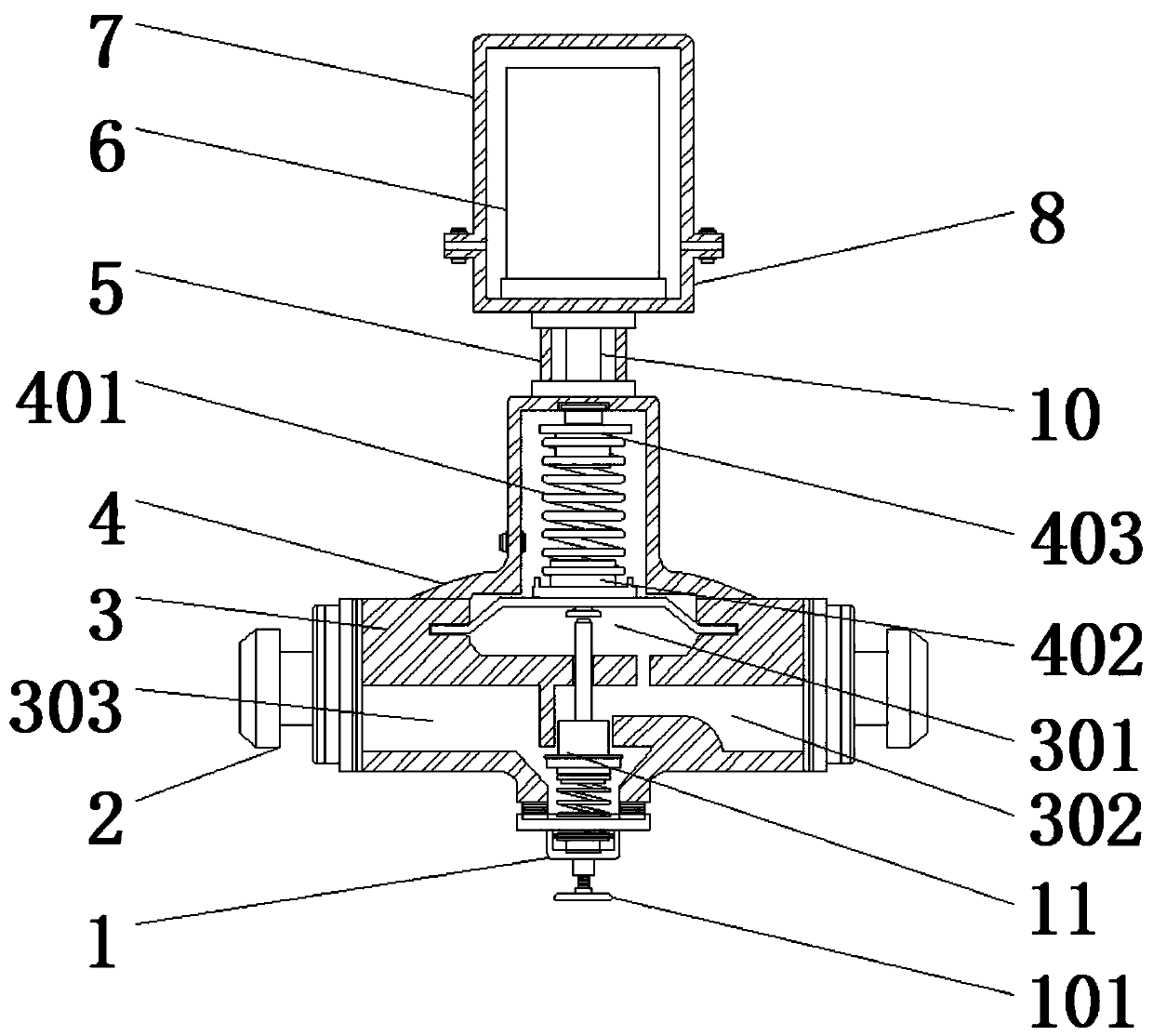
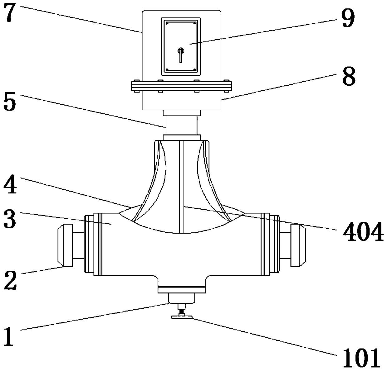
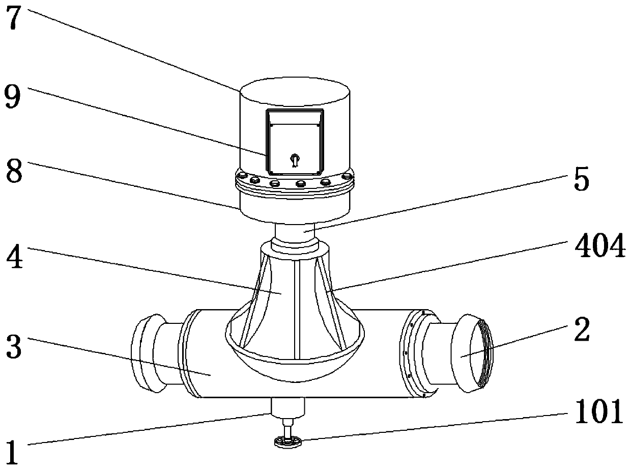

Image

  • Electromagnetic locking pressure reducing valve
  • Electromagnetic locking pressure reducing valve
  • Electromagnetic locking pressure reducing valve

Examples


Embodiment Construction

[0026] The following will clearly and completely describe the technical solutions in the embodiments of the present invention with reference to the accompanying drawings in the embodiments of the present invention. Obviously, the described embodiments are only some, not all, embodiments of the present invention. Based on the embodiments of the present invention, all other embodiments obtained by persons of ordinary skill in the art without making creative efforts belong to the protection scope of the present invention.

[0027] In the description of the present invention, it should be noted that the terms "upper", "lower", "inner", "outer", "front end", "rear end", "both ends", "one end", "another end" The orientation or positional relationship indicated by etc. is based on the orientation or positional relationship shown in the drawings, and is only for the convenience of describing the present invention and simplifying the description, rather than indicating or implying that ...


PUM


Abstract

The invention discloses an electromagnetic locking pressure reducing valve. The valve comprises a bottom valve body and a valve seat body. An air inlet channel and an air outlet channel which are communicated are formed in the two sides of the valve body. A communicated mounting cover body is fixedly mounted at the bottom of the valve body; a thread adjusting knob is fixedly mounted at the bottomof the mounting cover body; a sealing piece is fixedly mounted in the mounting cover body through a second reset spring; a diaphragm air chamber is arranged in the portion, above the air inlet channeland the air outlet channel, of the valve body; an elastic diaphragm is embedded in the diaphragm air chamber; the diaphragm air chamber communicates with the air outlet channel through a damping pipe; and an overflow valve is fixedly installed in the center of THE second reset spring. According to the invention, a worker can manually adjust the pressure reducing operation under the condition of power failure, the influence of power failure on the working progress is avoided or reduced, the situation that air flow vibrates during flow guiding due to too high internal pressure is avoided or reduced, and the smoothness and stability during operation are guaranteed.

Description

technical field [0001] The invention relates to the technical field of control valves, in particular to an electromagnetic locking pressure reducing valve. Background technique [0002] The pressure reducing valve is a valve that reduces the inlet pressure to a certain required outlet pressure through adjustment, and relies on the energy of the medium itself to keep the outlet pressure automatically stable. From the perspective of fluid mechanics, the pressure reducing valve is a local resistance that can The changing throttling element, that is, by changing the throttling area, the flow rate and the kinetic energy of the fluid are changed, resulting in different pressure losses, so as to achieve the purpose of decompression, and then rely on the adjustment of the control and regulation system to make the pressure fluctuation after the valve and The spring force is balanced to keep the pressure behind the valve constant within a certain error range; [0003] The function of...

Claims


Application Information

Patent Timeline
Patent Type & Authority Applications(China)
IPC IPC(8): F16K31/06F16K27/02F16K17/22
CPCF16K17/22F16K27/029F16K31/0655F16K31/0675
Inventor 李文静
Owner 苏州荔记得机械工程科技有限公司
Learn More