Metallization lamination layer, manufacturing method thereof and electronic equipment comprising metallized laminate

A metallization and metal layer technology, which is applied in semiconductor/solid-state device manufacturing, circuits, electrical components, etc., can solve problems such as increased manufacturing costs, integrated circuit short circuit or open circuit faults, and achieve increased integration density, reduced line width or The effect of CD and interval

Active Publication Date: 2020-04-07
INST OF MICROELECTRONICS CHINESE ACAD OF SCI
View PDF4 Cites 3 Cited by
  • Summary
  • Abstract
  • Description
  • Claims
  • Application Information

AI Technical Summary

Problems solved by technology

In addition, it is difficult to align the metal lines with the vias, which can lead to short or

Method used

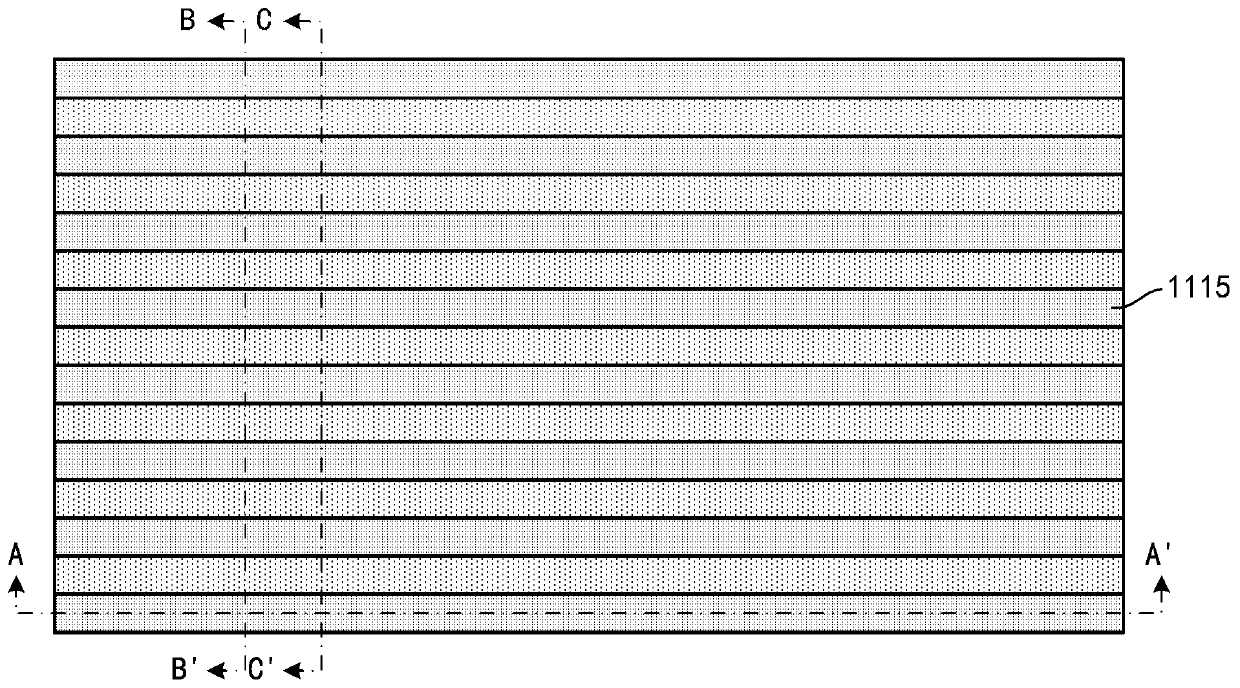

Image

  • Metallization lamination layer, manufacturing method thereof and electronic equipment comprising metallized laminate
  • Metallization lamination layer, manufacturing method thereof and electronic equipment comprising metallized laminate
  • Metallization lamination layer, manufacturing method thereof and electronic equipment comprising metallized laminate

Examples


Embodiment Construction

[0013] Hereinafter, embodiments of the present disclosure will be described with reference to the drawings. It should be understood, however, that these descriptions are exemplary only, and are not intended to limit the scope of the present disclosure. Also, in the following description, descriptions of well-known structures and techniques are omitted to avoid unnecessarily obscuring the concepts of the present disclosure.

[0014] Various structural schematic diagrams according to embodiments of the present disclosure are shown in the accompanying drawings. The figures are not drawn to scale, with certain details exaggerated and possibly omitted for clarity of presentation. The shapes of the various regions and layers shown in the figure, as well as their relative sizes and positional relationships are only exemplary, and may deviate due to manufacturing tolerances or technical limitations in practice, and those skilled in the art will Regions / layers with different shapes, ...


PUM


Abstract

The invention discloses a metallization lamination layer, a manufacturing method thereof and electronic equipment comprising the metallization lamination layer. According to an embodiment, the metallization lamination layer may include at least one interconnect line layer and at least one via hole layer alternately disposed on a substrate. At least one pair of adjacent interconnection line layer and via hole layer in the metallization lamination layer comprises interconnection lines in the interconnection line layer and via holes in the via hole layer. The interconnect line layers are closer to the substrate than the via hole layer. The outer peripheral side wall of the via holes on at least a portion of the interconnect lines does not exceed the outer peripheral side wall of the at leasta portion of the interconnect lines.

Description

technical field [0001] The present disclosure relates to the field of semiconductors, and more particularly, to metallization stacks, methods of making the same, and electronic devices including such metallization stacks. Background technique [0002] With the continuous miniaturization of semiconductor devices, it is becoming more and more difficult to manufacture high-density interconnect structures because of the need for extremely thin metal lines (meaning small grain size, excessive barrier layer thickness and thus high resistance) and Extremely small line spacing (meaning misalignment, difficulty filling contact holes). In addition, it is difficult to align the metal lines with the vias, which can lead to short or open failures in the integrated circuit (IC), and thus increase the manufacturing cost of the IC. Contents of the invention [0003] In view of this, an object of the present disclosure is at least in part to provide a metallization stack, a method of manu...

Claims


Application Information

Patent Timeline
IPC IPC(8): H01L23/48H01L21/768H01L23/485H01L21/60
CPCH01L23/481H01L21/76805H01L24/20H01L24/19H01L2224/0231H01L2224/02331H01L2224/02333H01L2224/02381H01L21/76885H01L21/7682H01L23/528H01L21/76816H01L21/76847H01L23/53242H01L21/76801H01L21/7685H01L23/5226H01L23/53209H01L23/53257H01L23/5329
Inventor 朱慧珑
Owner INST OF MICROELECTRONICS CHINESE ACAD OF SCI
Why Eureka
Try Eureka