
Pulse per second time signal synchronization device and method

A technology of time signal and synchronization device, applied in multiplex communication, time division multiplexing system, electrical components, etc., can solve the problems of asymmetric structure design, inconvenient standardized production, etc., to achieve standardized production of equipment, easy to The effect of equipment standardized production

Inactive Publication Date: 2020-04-07
BEIJING INST OF RADIO METROLOGY & MEASUREMENT
View PDF7 Cites 9 Cited by
  • Summary
  • Abstract
  • Description
  • Claims
  • Application Information

AI Technical Summary

Problems solved by technology

[0003] The present invention provides a second pulse time signal synchronization device and method, which solves the problem that the existing device and method have structural asymmetry design and are not convenient for standardized production in engineering

Method used


Image

  • Pulse per second time signal synchronization device and method
  • Pulse per second time signal synchronization device and method
  • Pulse per second time signal synchronization device and method

Examples


no. 2 Embodiment

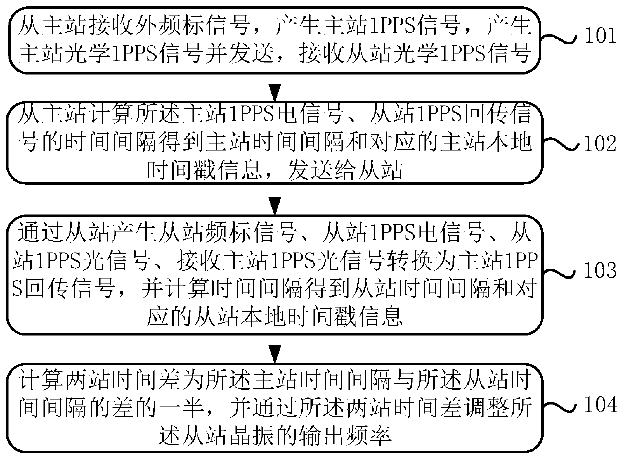
[0045] image 3 It is an embodiment of a process flow of a second pulse time signal synchronization method, which can be used in the first and or second embodiments of the present invention, and specifically includes the following steps:

[0046] Step 101: Receive the external frequency standard signal from the master station, generate the master station frequency standard signal, the master station 1PPS electrical signal, generate the master station 1PPS optical signal and send it, receive the slave station 1PPS optical signal and convert it into a slave station 1PPS return signal.

[0047] In step 101, under the control of the PID module of the master station, the crystal oscillator of the master station keeps synchronization with the external frequency standard signal.

[0048] Step 102, calculate the time interval of the 1PPS electrical signal of the master station and the 1PPS return signal of the slave station from the master station to obtain the time interval of the ma...


PUM


Abstract

The invention discloses a pulse per second time signal synchronization device and method, and solves the problems that an existing device and method are asymmetrically designed in structure, and engineering standardized production is inconvenient. The device is used for realizing time synchronization between a slave station and a master station, wherein the master station is used for receiving anexternal frequency standard signal and generating a master station frequency standard signal, a master station 1PPS electric signal and a master station 1PPS optical signal, receiving a slave station1PPS optical signal, calculating a time interval between the master station 1PPS electric signal and the slave station 1PPS return signal to obtain a master station time interval, the slave station and the master station have the same structure and the slave station is used for receiving a master station 1PPS optical signal and a master station time interval, generating a slave station frequency standard signal, a slave station 1PPS electric signal and a slave station 1PPS optical signal, calculating a time interval between the slave station 1PPS electric signal and the master station 1PPS return signal to obtain a slave station time interval, and calculating the time difference between the two stations, and adjusting the output frequency of the slave station crystal oscillator. The methodis applied to the device. The device and the method are high in real-time performance and engineering practicability.

Description

technical field [0001] The invention relates to the technical field of optical fiber timing, in particular to a pulse-per-second time signal synchronization device and method. Background technique [0002] Since the optical fiber one-way time transfer synchronization system will be affected by link path changes, it is also necessary to maintain the stability of the optical fiber transfer link in real time during the time synchronization process, that is, to actively control the link length. The difference is that the optical fiber two-way time transfer and synchronization system is based on the two-way transmission principle, even when the link length changes, it can still measure and obtain high-precision clock error to achieve high-precision time synchronization. However, in most optical fiber two-way time synchronization systems at present, the slave station realizes time synchronization by actively controlling the time base of the master station, and the slave station do...

Claims


Application Information

Patent Timeline
Patent Type & Authority Applications(China)
IPC IPC(8): H04J3/06
CPCH04J3/0685
Inventor 杨宏雷王海峰王学运易航王宏博张升康
Owner BEIJING INST OF RADIO METROLOGY & MEASUREMENT
Learn More