Releasable embolic spring coil system

A coil and embolization technology, applied in the field of detachable embolization coil system, can solve the problems of complex structure and inconvenient operation, and achieve the effect of simple operation and sensitive response

Pending Publication Date: 2020-04-10
BEIJING AMSINO MEDICAL
View PDF2 Cites 7 Cited by
  • Summary
  • Abstract
  • Description
  • Claims
  • Application Information

AI Technical Summary

Problems solved by technology

[0012] The purpose of the present invention is to propose a safe and reliable detachable embolic coil system, there

Method used


Image

  • Releasable embolic spring coil system
  • Releasable embolic spring coil system
  • Releasable embolic spring coil system

Examples


Embodiment 1

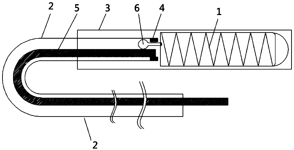
[0046] This embodiment provides a detachable embolization coil system, its structure is as follows figure 1 shown. The detachable embolic coil system includes: a delivery device, a detachment device and an embolic coil 1; wherein:

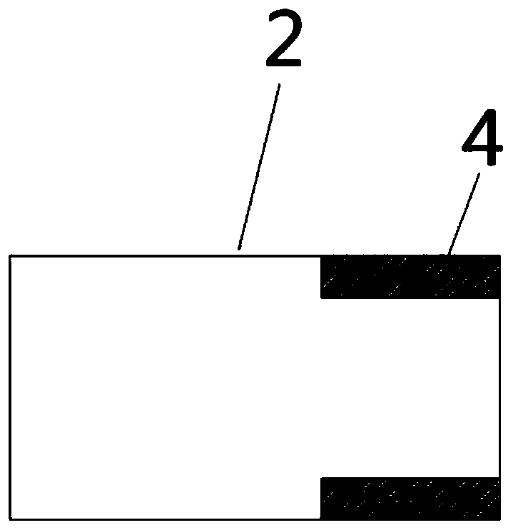
[0047] The delivery device comprises a push rod 2 and an introduction sheath 3; the push rod 2 is hollow tubular, and its far-end inner wall is provided with a stopper 4 (such as figure 2 shown), the distal end of the push rod 2 is inserted into the proximal part of the introduction sheath 3, and the embolism coil 1 is arranged in the introduction sheath 3;

[0048] The release device comprises a release wire 5 and a release ball 6, the release wire 5 is arranged inside the push rod 2, and the distal end of the release ball 6 is connected with the embolism coil 1;

[0049] In the limit state, the release wire 5 and the limit part 4 limit the release ball 6 inside the push rod 2;

[0050] When released, the release wire 5 is pulled at the proxim...

Embodiment 2

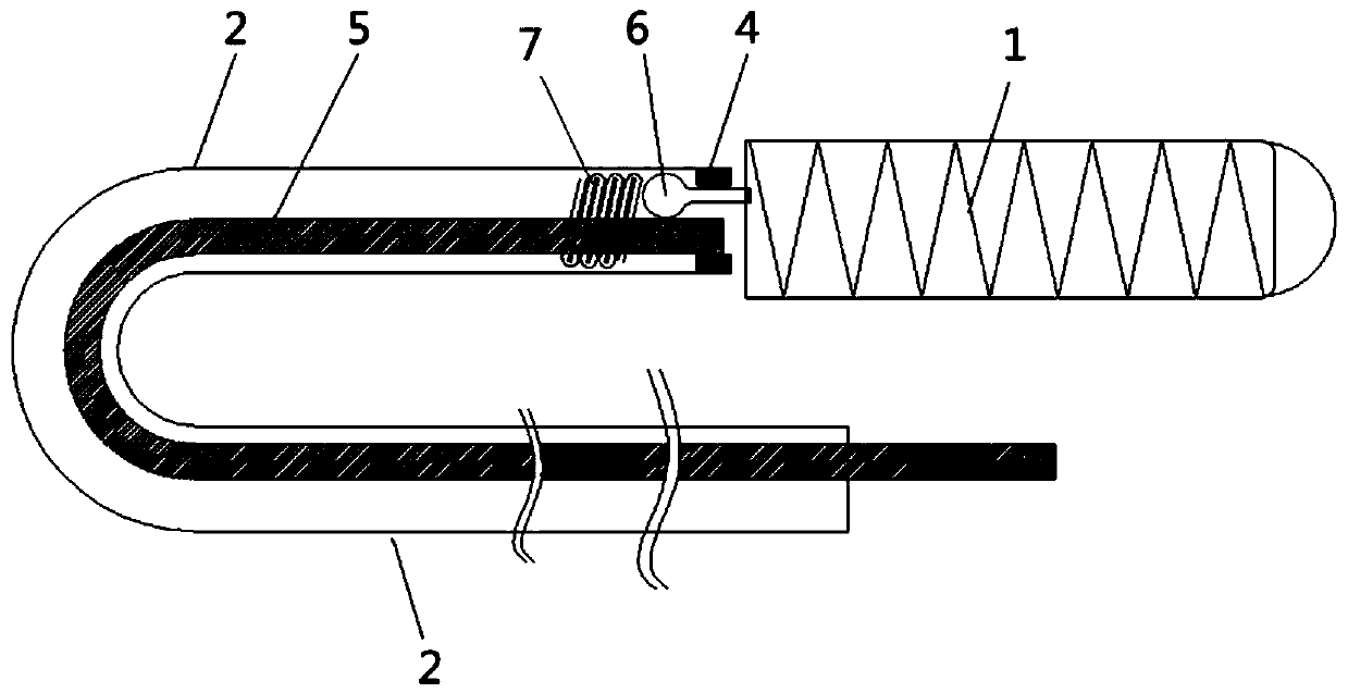
[0052] This embodiment provides a detachable embolization coil system, its structure is as follows image 3 shown. The detachable embolic coil system includes: a delivery device, a detachment device and an embolic coil 1; wherein:

[0053] The delivery device includes a pusher rod 2 and an introduction sheath 3 (not shown in the figure); the pusher rod 2 is hollow tubular, and the inner wall of its distal end is provided with a limiter 4, and the distal end of the pusher rod 2 is inserted into the proximal part of the introduction sheath 3 , the embolism coil 1 is set in the introduction sheath 3;

[0054] The release device comprises a release wire 5, a release ball 6, a pre-compressed elastic coil 7, and the release wire 5 is arranged in the inside of the push rod 2, and the distal end of the release ball 6 is connected with the embolism coil 1; the pre-compressed elastic coil 7 It is located in the push rod 2 and is assembled to give the elastic coil a pre-compression for...

Embodiment 3

[0058] This embodiment provides a detachable embolization coil system, its structure is as follows Figure 8 shown. The detachable embolic coil system includes: a delivery device, a detachment device and an embolic coil 1; wherein:

[0059] The delivery device includes a push rod 2 and an introduction sheath 3; the push rod 2 is hollow tubular, and a stopper 4 is provided on the inner wall of its distal end, the distal end of the push rod 2 is inserted into the proximal part of the introduction sheath 3, and the embolism coil 1 is set in the introduction sheath 3;

[0060] The release device comprises release wire 5, release ball 6, pre-stretched elastic coil 8, and release wire 5 is arranged in the inside of push rod 2, and the distal end of release ball 6 is connected together with embolism coil 1; the elastic force of pre-stretch The coil 8 is located in the embolic coil 1, and its proximal end is fixedly connected to the distal end of the release ball 6, and the distal e...


PUM

PropertyMeasurementUnit
Wire diameteraaaaaaaaaa

Abstract

The invention provides a releasable embolic spring coil system. The releasable embolism spring ring system comprises a conveying device, a release device and an embolism spring ring, wherein the conveying device comprises a push rod which is of a hollow pipe shape; limiting parts are arranged on the inner wall of the far end of the push rod; the release device comprises a release wire and a release ball; the release wire is arranged in the push rod; the far end of the release ball is connected with the embolism spring ring; in a limiting state, the release ball is limited in the push rod by the release wire and the limiting parts; and in a release state, the release ball is separated from limiting and is separated from the push rod from a far end position; thus, the embolism spring ring isreleased. The releasable embolism spring ring system provided by the invention can stably convey a spring ring into a position needing thrombus occlusion in a human body; the spring ring is easily and mechanically released; thus, the releasable embolism spring ring system is simple in operation and sensitive in response, and does not damage blood vessels.

Description

technical field [0001] The invention relates to a detachable embolization coil system, which belongs to the technical field of vascular stent preparation. Background technique [0002] Intracranial Aneurysm (Intracranial Aneurysm, AN) is a common disease with a prevalence rate of 1%-5%. Because intracranial aneurysms are generally small, about 50 to 80% of patients with AN will not rupture and are not life-threatening. However, once AN ruptures, it will manifest as primary subarachnoid hemorrhage (SAH) and cause acute stroke, which is a serious and life-threatening common disease. About 10% of acute strokes are due to ruptured intracranial aneurysms. The World Health Organization survey shows that the incidence rate in China is about 2.0 / 100,000 person-years, and it is also reported that it is 6-20 / 100,000 people per year [0003] The treatment of primary subarachnoid hemorrhage caused by AN rupture is surgical clipping and endovascular embolization. With the advancement...

Claims


Application Information

Patent Timeline
IPC IPC(8): A61B17/12
CPCA61B17/12113A61B17/1214A61B2017/1205A61B2017/12068A61B2017/12072
Inventor 徐建国王云兵马晓意周利锋李志龙倪华丽何福桂
Owner BEIJING AMSINO MEDICAL
Why Eureka
Try Eureka