
In-furnace denitration system and in-furnace denitration process

A denitrification and boiler technology, which is applied in the direction of dispersed particle filtration, lighting and heating equipment, gas treatment, etc., can solve the problem of high-efficiency use of temperature coal powder particles waste, etc., to increase the service life, increase the area, and the structure is not complicated Effect

Inactive Publication Date: 2020-04-10
江苏天莱环保工程有限公司
View PDF20 Cites 2 Cited by
  • Summary
  • Abstract
  • Description
  • Claims
  • Application Information

AI Technical Summary

Problems solved by technology

[0006] In order to solve the above problems, the present invention provides an in-furnace denitrification system and process, which effectively avoids that the flue gas discharged from the boiler in the prior art passes through the denitrification system and is directly discharged to the chimney without efficient use of flue gas with a high temperature , There are still unburned pulverized coal particles in the flue gas that are all directly discharged to the chimney so that all the pulverized coal particles are wasted

Method used


Image

  • In-furnace denitration system and in-furnace denitration process
  • In-furnace denitration system and in-furnace denitration process
  • In-furnace denitration system and in-furnace denitration process

Examples


Embodiment 1

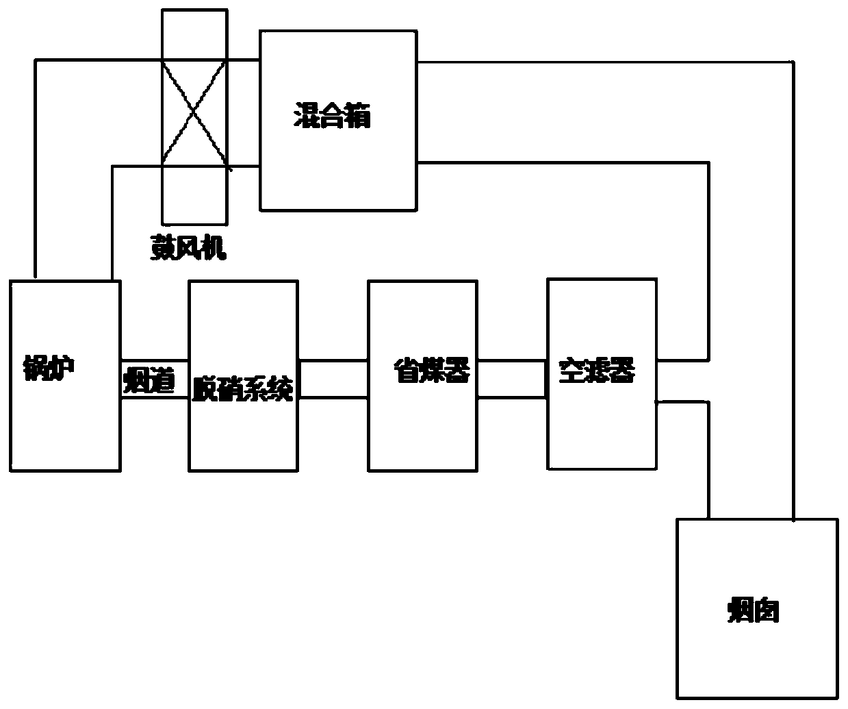
[0038] Such as Figure 1-Figure 5 As shown, the denitration system in the furnace includes a boiler, a flue of the boiler, a denitration system, an economizer, an air filter, a mixing box and a return channel; the flue gas outlet of the boiler communicates with one end of the flue of the boiler, and the The flue of the boiler is used to discharge the flue gas of the boiler that flows out through the flue gas outlet; the flue of the boiler is sequentially connected with a denitrification system, an economizer and an air filter in a direction away from the boiler; The other end of the flue of the boiler is communicated with the chimney; the flue part between the air filter and the chimney is also communicated with one end of the return channel, and the other end of the return channel is communicated with the boiler; A mixing box and a blower are sequentially connected to the channel in the direction of approaching the boiler. Through such a structure, the blower can be used to ...

Embodiment 2

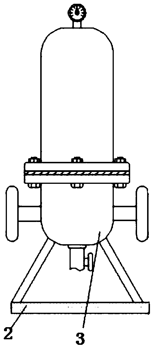
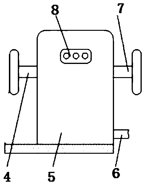
[0047] Such as Figure 1-Figure 5As shown, the denitrification system in the furnace includes a pipeline mixer, and the pipeline mixer and the high-pressure centrifugal fan are all communicated with the multifunctional filter through pipelines; the multifunctional filter includes a support platform 2 fixed on the ground surface, via The introduction of the support platform 2 increases the range of the connection between the filter body 3 and the hollow container 5 and the ground surface, and increases the reliability of the multifunctional filter when it is used. The two sides of the upper end of the support platform 2 The filter main body 3 and the hollow container 5 are respectively fixed, and the inner surface of the hollow container 5 is fixedly connected with a heat-resistant sheet 21, and the heat-resistant sheet 21 is introduced to achieve the effect of heat insulation and prevent heat energy from being transferred to the outside. The upper end on the left side of the h...


PUM


Abstract

The invention relates to an in-furnace denitration system and an in-furnace denitration process. The system comprises a boiler, a boiler flue channel, a denitration system body, an economizer, an airfilter, a mixing box and a reflux channel, wherein the flue gas outlet of the boiler is communicated with one end of the boiler flue channel, the boiler flue channel is used for discharging flue gas,flowing out of the flue gas outlet, of the boiler, the denitration system, the economizer and the air filter are sequentially communicated with the boiler flue channel in the direction away from the boiler, the other end of the boiler flue channel is communicated with a chimney, the flue channel between the air filter and the chimney is further communicated with one end of the reflux channel, andthe other end of the reflux channel is communicated with the boiler. According to the invention, by combining with other structures or methods, the defects that flue gas discharged by a boiler is completely and directly discharged to a chimney after passing through a denitration system so as not to efficiently use the flue gas with high temperature, and incompletely-combusted coal powder particlesin the flue gas are completely and directly discharged to the chimney so as to completely waste the coal powder particles are effectively overcome.

Description

technical field [0001] The present invention relates to the technical field of denitrification, and also relates to the technical field of denitrification in a furnace, in particular to an in-furnace denitrification system and process. Background technique [0002] The importance of preventing environmental pollution has been sharply raised as a worldwide problem. Removing nitrogen oxides from combustion flue gas is a necessary means to prevent environmental pollution. Denitrification is essentially the removal of nitrogen oxides from combustion flue gas. process of things. [0003] The more mainstream denitrification principle for boilers in the world is to use the flue gas discharged from the boiler to pass through the denitrification system and then be discharged to the chimney through the flue. All of this is directly discharged to the chimney, but there is no efficient use of flue gas with a high temperature, and the flue gas There are also unburned pulverized coal par...

Claims


Application Information

Patent Timeline
Patent Type & Authority Applications(China)
IPC IPC(8): B01D53/86B01D53/90B01D53/56F22D1/00F23J15/02B01D46/00B01D46/42
CPCB01D53/8631B01D53/90B01D46/4218B01D46/00F22D1/00F23J15/025B01D2258/0283
Inventor 陈治国杨义球赵起
Owner 江苏天莱环保工程有限公司
Learn More