Water discharge device of vehicle air cylinder

A technology of drainage device and air storage tank, which is applied in the directions of air handling device, pipeline arrangement, vehicle components, etc., can solve the problems of low installation position of the air storage tank structure, air leakage of the air brake system, affecting the power performance, etc., so as to reduce the collision Probability of touching road protruding obstacles, improving air tightness, and convenient operation

Inactive Publication Date: 2020-04-10
十堰安凯汽车零部件有限公司
View PDF0 Cites 0 Cited by
  • Summary
  • Abstract
  • Description
  • Claims
  • Application Information

AI Technical Summary

Problems solved by technology

Often due to the limited layout space, the installation position of the air storage tank is relatively low. The conventional form of the water discharge valve cannot completely ensure that the water discharge valve does not touch the ground obstacles when the vehicle is running. This defect may cause air leakage in the air brake system and insufficient braking force. And the energy consumption of the whole vehicle increases, which affects the power performance; and because the air storage tank of the passenger car produces more condensed water and impurities, it is necessary to frequently drain the air storage tank, and the existing air tank of the passenger car is generally arranged in the middle of the chassis frame , and the drain valve is generally installed at the bottom of the air storage tank to discharge the condensed water accumulated in the air storage tank
When drainage is required, the driver needs to drill to the bottom of the bus and manually pull the drain ring on the drain valve to drain the water in the air storage tank. The operation is time-consuming and inconvenient

Method used


Image

  • Water discharge device of vehicle air cylinder
  • Water discharge device of vehicle air cylinder

Examples


Embodiment Construction

[0020] The following will clearly and completely describe the technical solutions in the embodiments of the present invention with reference to the accompanying drawings in the embodiments of the present invention. Obviously, the described embodiments are only some, not all, embodiments of the present invention. Based on the embodiments of the present invention, all other embodiments obtained by persons of ordinary skill in the art without making creative efforts belong to the protection scope of the present invention.

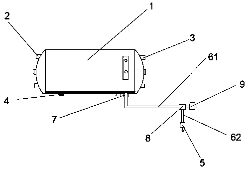
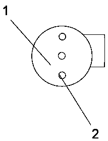
[0021] see figure 1 and figure 2 , the present invention provides a technical solution: a drainage device for a vehicle air storage tank, including an air storage tank shell 1, an air inlet port 2, an air outlet port 3, a mixed liquid 4, a water discharge valve 5, a water discharge pipe 6, and a water discharge valve mounting seat 7. The three-way joint 8 and the drain valve 9, the air storage tank shell 1 is a cylindrical structure, the two ends of the air ...


PUM


Abstract

The invention discloses a water discharge device of a vehicle air cylinder. An air cylinder shell is of a cylindrical structure, an air inlet port and an air outlet port are formed at the two ends ofthe air cylinder shell correspondingly, a mixed liquid is arranged at the bottom in the air cylinder shell, a water drain valve is arranged at the right lower part of the air cylinder shell through awater drain valve installation base, the water drain valve is arranged below the water drain valve installation base, the water drain valve installation base is arranged below the air cylinder shell,a water drain pipe is arranged between the water drain valve and the water drain valve installation base and is in threaded connection with the water drain valve installation base, a three-way connector is arranged at the tail end of the water drain pipe, and the rear end of the three-way connector is connected with a water discharge valve and the water drain valve. The water drain valve and the water discharge valve are arranged below the air cylinder, the water drain efficiency is effectively improved through the connection relation of the water drain pipe, operation is easy, and use is convenient.

Description

technical field [0001] The invention relates to the technical field of automobile manufacturing, in particular to a drainage device for an air storage tank for a vehicle. Background technique [0002] The structure of the passenger car air storage tank in the prior art includes the air storage tank body, the air storage tank joint seat, the air storage tank water outlet and the manual water release valve; the air enters the air storage tank body after being compressed by the air compressor, filtered and dried, and the compressed air cools down. Excess water will be precipitated. After a long period of operation, the oil-water mixture will accumulate at the bottom of the air storage tank body. The operator regularly drains and checks the air storage tank body through the manual water release valve to ensure that the air brake system works reliably. Often due to the limited layout space, the installation position of the air storage tank is relatively low. The conventional form...

Claims


Application Information

Patent Timeline
Patent Type & Authority Applications(China)
IPC IPC(8): B60T17/00B60T17/04
CPCB60T17/004B60T17/043
Inventor 汪招军
Owner 十堰安凯汽车零部件有限公司
Why Eureka
Try Eureka