
Adjustable sludge cleaning device for sludge drying system

A sludge drying and cleaning device technology, applied in water/sludge/sewage treatment, dehydration/drying/thickened sludge treatment, special treatment targets, etc., can solve the hazards of decontamination personnel, consume a lot of labor, and affect work Efficiency and other issues to achieve the effect of improving work efficiency and service life, increasing production costs, and improving product quality

Inactive Publication Date: 2020-04-10
孟思明
View PDF7 Cites 0 Cited by
  • Summary
  • Abstract
  • Description
  • Claims
  • Application Information

AI Technical Summary

Problems solved by technology

[0002] The sludge distribution belt of the current sludge drying system is made of tough rubber material. It is located at the lower part of the shredder, connected end to end, and the driving motor at the bottom keeps rotating continuously to realize the conveying function of the distribution belt. Because granular sludge It is viscous. After running for a period of time, the phenomenon of sticky mud accumulation in the distribution belt is serious. The main problems that will occur are: after the distribution belt has mud accumulation, the belt load increases, and the motor load is too large, causing the motor to stop. The shredder is the sludge. It is an important part of the drying system, which is interlocked with the operation of the whole system, which will eventually lead to the shutdown of the entire drying line. The mud in the distribution belt prevents the production capacity of the entire drying line from being increased, which restricts the production capacity. Moreover, due to the current manual cleaning method Removing sticky mud will lead to frequent cleaning work, heavy load, a large amount of labor consumption, wear and tear on the distribution belt, and shorten the service life of the distribution belt. After cleaning, the sludge cannot enter the subsequent process section for treatment and can only be used as waste. After the mud sticks to the belt, due to the increase in viscosity, a large amount of granular sludge will fall and accumulate at the bottom of the distribution belt due to inertia, which will affect the working environment. In the prior art, for example, the invention patent with the application number 201621216691.X includes a reducer, one end of the reducer is connected with a U-shaped conveying trough, and the drive shaft of the reducer is connected with a spiral Shaft head, the outer surface of the spiral shaft head is connected with a shaftless helical roller, the top of the U-shaped conveying trough is equipped with a feed port, the bottom of the U-shaped conveying trough is provided with a leg, and the U-shaped conveying trough A mud discharge port is connected to the bottom of one end, the upper surface of the U-shaped conveying trough is equipped with a cover plate matching the notch of the U-shaped conveying trough, the combination of the spiral shaft head and the shaftless spiral roller forms a spiral thickening device, and The spiral concentrating device is connected with an air supply device, a U-shaped liner is provided at the connection between one end of the reducer and the U-shaped conveying trough, and the middle part of the U-shaped liner is provided with an installation shaft hole. The structure is simple, but there are many deficiencies and defects. In the existing equipment, there are defects in the design of the shaftless rotating roller. The connection between the shaftless rotating roller and the U-shaped conveying trough is unstable. It is suitable for easy to cause blockage of the U-shaped conveying trough. Causes damage to the shaftless rotating roller, increases the production cost of the enterprise, increases the workload of the maintenance personnel, makes the maintenance personnel easy to feel physical fatigue, and at the same time reduces the work efficiency, and the inclination angle of the legs cannot be adjusted, which reduces the transmission efficiency. situation, in order to avoid the above-mentioned technical problems, it is necessary to provide an adjustable sludge cleaning device for sludge drying system to overcome the defects in the prior art

Method used

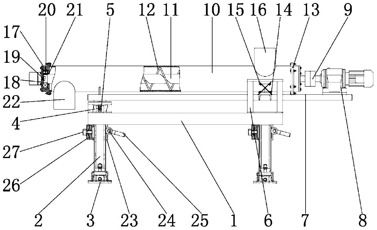

Image

  • Adjustable sludge cleaning device for sludge drying system
  • Adjustable sludge cleaning device for sludge drying system
  • Adjustable sludge cleaning device for sludge drying system

Examples


Embodiment Construction

[0019] The following will clearly and completely describe the technical solutions in the embodiments of the present invention with reference to the accompanying drawings in the embodiments of the present invention. Obviously, the described embodiments are only some, not all, embodiments of the present invention. Based on the embodiments of the present invention, all other embodiments obtained by persons of ordinary skill in the art without making creative efforts belong to the protection scope of the present invention.

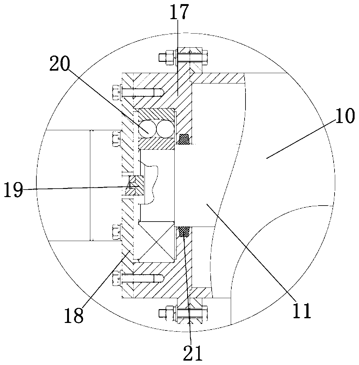
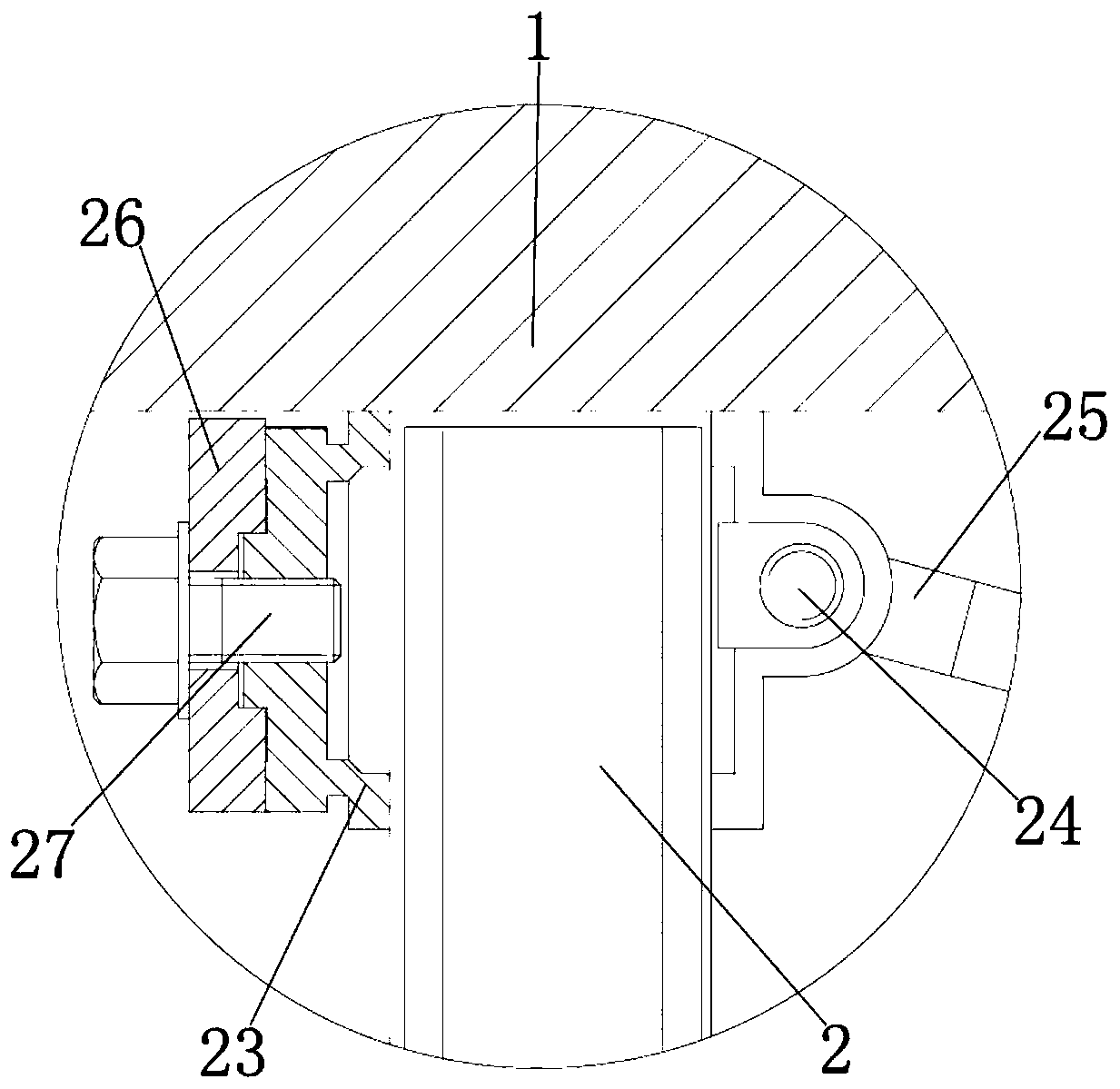
[0020] see Figure 1-3, the present invention provides a technical solution: an adjustable sludge cleaning device for a sludge drying system, including a bottom plate 1 for installing legs 2, and legs are installed on the left and right sides of the lower surface of the bottom plate 1 2. It is used to connect and fix the base plate 1. The outer wall of the leg 2 is sleeved with a splint 23, which is used to fix the leg 2 in the base plate 1 by pulling the hand...


PUM


Abstract

The invention discloses an adjustable sludge cleaning device for a sludge drying system. The adjustable sludge cleaning device comprises a bottom plate, supporting legs are installed on the left sideand the right side of the lower surface of the bottom plate, the upper surfaces of the supporting legs are connected with the lower surface of the bottom plate, the inner wall of a base is connected with the outer walls of the supporting legs, the outer walls of the supporting legs are movably connected with the inner wall of the bottom plate, and a support is installed on the upper surface of thebottom plate. According to the adjustable sludge cleaning device for a sludge drying system, a motor, a coupling and a rotating shaft are matched with one another; under the action of a stirring paddle, an alternating current servo motor is adopted, the rotating speed of the motor is adjusted by adjusting the power generated by current passing through the motor, the product quality of the adjustable sludge cleaning device for the sludge drying system is improved, the purchasing cost of users is saved, resource waste of the adjustable sludge cleaning device for the sludge drying system is avoided, and the adjustable sludge cleaning device is suitable for application and popularization.

Description

technical field [0001] The invention relates to the technical field of sludge cleaning, in particular to an adjustable sludge cleaning device used in a sludge drying system. Background technique [0002] The sludge distribution belt of the current sludge drying system is made of tough rubber material. It is located at the lower part of the shredder, connected end to end, and the driving motor at the bottom keeps rotating continuously to realize the conveying function of the distribution belt. Because granular sludge It is viscous. After running for a period of time, the phenomenon of sticky mud accumulation in the distribution belt is serious. The main problems that will occur are: after the distribution belt has mud accumulation, the belt load increases, and the motor load is too large, causing the motor to stop. The shredder is the sludge. It is an important part of the drying system, which is interlocked with the operation of the whole system, which will eventually lead t...

Claims


Application Information

Patent Timeline
IPC IPC(8): C02F11/12
CPCC02F11/12C02F2303/14
Inventor 孟思明
Owner 孟思明
Learn More