Landscape road floor tile and construction method thereof

A technology of floor tiles and roads, which is applied in the field of landscape road floor tiles and its construction, can solve the problems of inconvenient laying and replacement, complex structure, damaged floor tiles, etc., and achieve the effects of avoiding waste of construction waste, saving costs, and not being easily damaged

Active Publication Date: 2020-04-10
河南华植市政园林工程有限公司
View PDF7 Cites 1 Cited by
  • Summary
  • Abstract
  • Description
  • Claims
  • Application Information

AI Technical Summary

Problems solved by technology

[0005] Although the above invention patents can achieve wear-resistant, shock-absorbing and water-permeable functions, it is inevitable that large-scale equipment will enter the interior of the garden due to maintenance or construction reasons during garden construction. Due to the complex structure and high cost of the above-mentioned patents, it is inconvenient to lay and replace. Damage to one floor tile may also damage other adjacent floor tiles during the replacement process

Method used


Image

  • Landscape road floor tile and construction method thereof
  • Landscape road floor tile and construction method thereof
  • Landscape road floor tile and construction method thereof

Examples


Embodiment 1

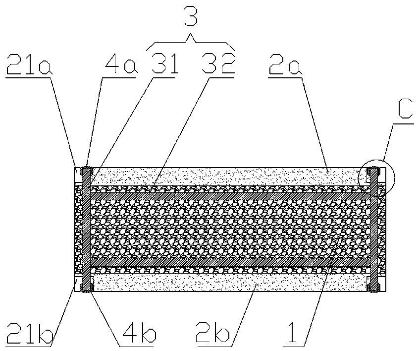
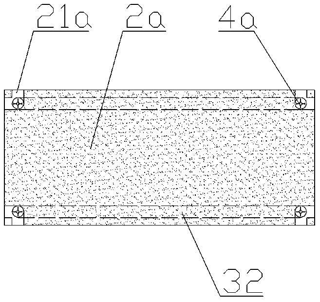
[0042] Such as Figure 1 ~ Figure 4 and Figure 7 ~ Figure 9 As shown, a landscape road floor tile includes a support layer 1, a water guide layer and a steel bracket 3 arranged in the support layer 1;

[0043] The support layer 1 is a block with gaps formed by bonding hard particles (such as construction waste, waste ceramics, or other hard material crushed uniform particles), and the upper and lower surfaces of the support layer 1 are parallel to each other; The water-conducting layer is a plate-shaped body with gaps formed by bonding elastic granular materials (such as rubber particles, plastic particles, etc.); The water-guiding layer 2a and the lower water-guiding layer 2b are respectively fixed on the upper and lower surfaces of the supporting layer 1, and the upper water-guiding layer 2a, the supporting layer 1 and the lower water-guiding layer 2b form a brick body; the floor tiles are in the shape of a cube, a cuboid, or a regular hexagonal prism Or other splicable r...

Embodiment 2

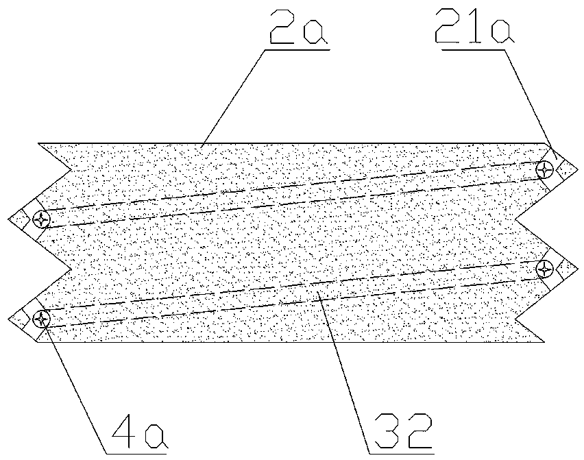
[0058] This embodiment is basically the same as Embodiment 1, the difference is that, as Figure 5 ~ Figure 6 As shown, there are more than two steel brackets 3, and the centers of the cross bars 32 of the two or more steel brackets 3 are misaligned and cross each other.

[0059] Such as Figure 5 As shown, when there are three steel brackets 3, the two cross bars 32 of the second steel bracket 3 are located between the two cross bars of the first steel bracket 3, and the two cross bars 32 of the third steel bracket 3 are located Between the two cross bars 32 of the second steel bracket 3 .

[0060] The cross bars 32 of two or more steel brackets 3 are misaligned and intersected with each other, which is mainly applied to regular polygonal columnar floor tiles, because they have no length direction during application, and each steel bracket 3 should be evenly distributed to strengthen the floor tiles as a whole.

[0061] The construction method of any one of the above-mentio...


PUM


Abstract

The invention relates to a landscape road floor tile, which comprises a supporting layer, water guide layers and a steel support arranged on the supporting layer, wherein the supporting layer is a blocky body which is formed by bonding hard particles and is provided with gaps, and the upper surface and the lower surface of the supporting layer are parallel to each other; the water guide layers aresheet-shaped bodies which are formed by bonding an elastic particle material and are provided with gaps; the water guide layers are respectively fixed on the upper surface and the lower surface of the supporting layer; and cross rods of the steel support are embedded in the supporting layer, the end parts of vertical rods of the steel support penetrate through the supporting layer upwards or downwards in the vertical direction and extend into the water guide layer. The floor tile further comprises a protective cap and a connecting accessory. The floor tiles can be connected with each other toform a whole, and individual floor tiles can be replaced quickly when being damaged. The floor tile is simple in structure, firm, durable and convenient to use.

Description

technical field [0001] The invention relates to the field of garden landscape roads, in particular to a landscape road floor tile and a construction method thereof. Background technique [0002] Landscape road is a very important part of landscape engineering. The quality of the road is directly related to the emotions of people walking on the road and the first impression of an area. For foreigners, the quality of a road is the evaluation of an area. An important part of. [0003] The paving of garden landscape roads refers to the use of any hard natural or artificial paving materials to decorate the road surface. Garden paving includes garden roads, squares, activity venues, building floors, etc.; garden paving is generally made of marble or Regular materials such as permeable bricks are paved after a certain planning and design. [0004] The invention patent with the application number 201510699866.0 and the authorized announcement number CN105200896B discloses a wear-r...

Claims


Application Information

Patent Timeline
Patent Type & Authority Applications(China)
IPC IPC(8): E01C11/22E01C5/04
CPCE01C5/04E01C11/225E01C2201/06E01C2201/14E01C2201/20
Inventor 井立兰王斌邢康丽祁小宝王义成
Owner 河南华植市政园林工程有限公司
Why Eureka
Try Eureka