
Stiffened steel concrete connecting joint and application method thereof

A technology for connecting joints and concrete, which is applied in the direction of construction and building structure, and can solve problems such as insufficient anchorage length, influence on the strength of steel columns, and errors in drilling holes, so as to facilitate quality control, improve operation efficiency, and ensure anchorage quality Effect

Pending Publication Date: 2020-04-10
GUANGZHOU HOUSES DEV CONSTR
View PDF0 Cites 0 Cited by
  • Summary
  • Abstract
  • Description
  • Claims
  • Application Information

AI Technical Summary

Problems solved by technology

[0005] 1. There is an error in the drilling, which makes the beam gluten difficult to wear;
[0006] 2. Even if the beam gluten can pass through, it is difficult to completely avoid it when passing through in two directions; too many holes even directly affect the strength of the steel column
[0008] 1. When the number of rows of beam gluten is small, it can be solved; but when there are many rows of beam gluten, there is still the problem of insufficient anchorage length, and the welding volume is large
[0009] 2. Welding first, the stirrups are not easy to wear; after welding, due to errors, it is necessary to add a lining plate when welding the beam gluten
[0011] 1. The welding quality of threaded sleeves is not easy to guarantee; when the quantity is large, there are also problems of large welding volume and high cost;
[0012] 2. The threaded connection must be implemented before the beam stirrups are pierced; the stirrups need to be installed in sequence, which is inefficient

Method used


Image

  • Stiffened steel concrete connecting joint and application method thereof
  • Stiffened steel concrete connecting joint and application method thereof
  • Stiffened steel concrete connecting joint and application method thereof

Examples


Embodiment 1

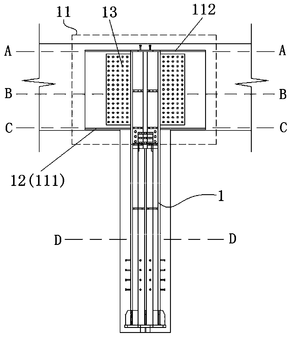
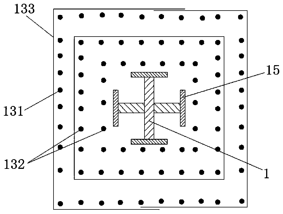
[0051] Such as Figure 1-9 As shown, this embodiment provides a steel-concrete connection node, including steel columns 1 and several beams 2 .

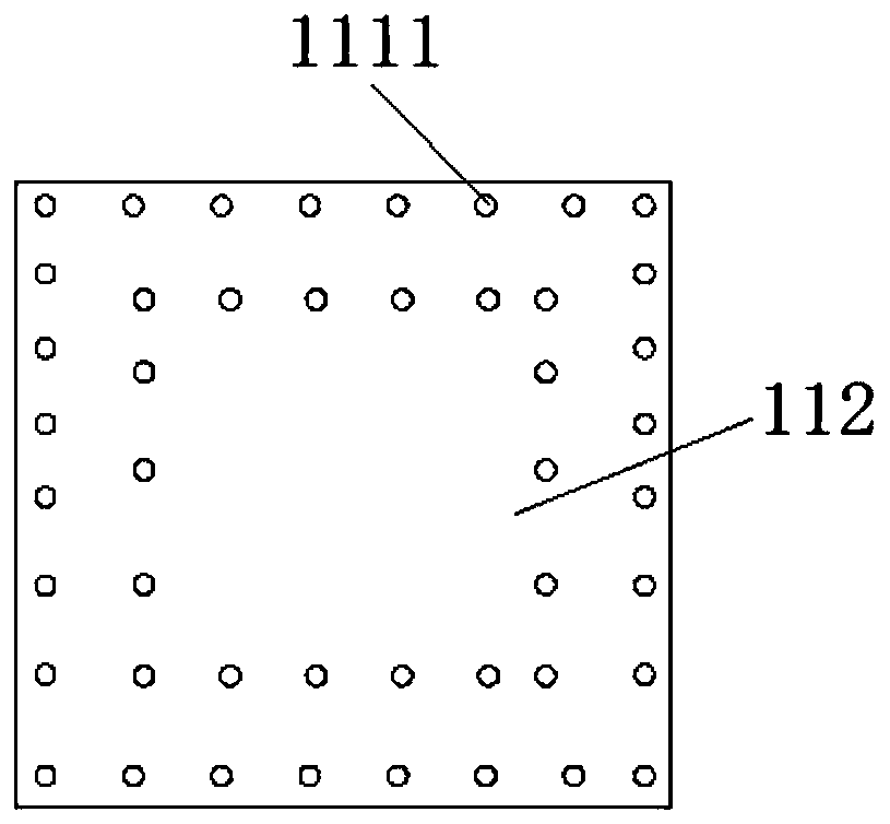
[0052] Further, the beam connection part 11 is arranged on the steel column 1, and the bottom end of the beam connection part 11 is provided with several connection steel plates 111, and the connection steel plates 111 are provided with via holes 1111, and the several connection steel plates 111 It is welded and connected with the shaped steel column 1 to form a support platform 12 , and several node steel bars pass through the through holes 1111 to form a reinforcement cage 13 on the support platform 12 .

[0053] As a preferred solution, a top steel plate 112 is provided at the top of the beam connecting portion 11, and a plurality of via holes 1111 are also provided on the top steel plate 112; so that on the shaped steel column 1, the A space is formed between the top steel plate 112 and the support platform 12 for setting the re...


PUM


Abstract

The invention provides a stiffened steel concrete connecting joint and an application method of the stiffened steel concrete connecting joint. The stiffened steel concrete connecting joint comprises asection steel column and multiple beam surface ribs. A beam connecting portion is arranged on the section steel column, multiple connecting steel plates are arranged at the bottom end of the beam connecting portion, via holes are formed in the connecting steel plates, the multiple connecting steel plates and the section steel column are connected in a welded manner to form a supporting platform,multiple joint rebars penetrate through the via holes, and a reinforcement cage is formed on the supporting platform; and the multiple beam surface ribs stretch into the reinforcement cage, and the length, allowing the beam surface ribs to stretch in, in the reinforcement cage is larger than or equal to the pre-anchoring lengths of the beam surface ribs. The sectional dimension of an original section steel column can be fully utilized, and the construction efficiency of the position of the connecting joint is improved while it is guaranteed that the beam surface ribs are fully anchored.

Description

technical field [0001] The invention belongs to the technical field of construction engineering, and in particular relates to a steel-concrete connection node and a construction method thereof. Background technique [0002] In the traditional connection work of reinforced concrete joints, when there are many layers of beam gluten, there will be situations where the beam gluten cannot be anchored into the column; for example, when there are three or more rows of beam gluten, due to the Due to the limited space, the beam gluten cannot be fully anchored into the reinforced concrete joints at this time, which directly affects the connection construction quality at the joints. [0003] In order to solve the above-mentioned problem of insufficient anchorage length, the traditional methods are as follows: [0004] The first method is to drill holes on the flange of the steel column for the penetration of beam gluten to increase the anchorage length; but in this method, [0005] 1...

Claims


Application Information

Patent Timeline
IPC IPC(8): E04B1/58
CPCE04B1/58
Inventor 田景杨龙永焯庄智严王志强谭振烽翁文彪罗林昕
Owner GUANGZHOU HOUSES DEV CONSTR
Learn More